OWNER’S MANUAL Version 1.
Version 1.
Warranty iConnectivity warrants to the original purchaser that this unit is free of defects in materials and workmanship under normal use and maintenance for a period of one (1) year from the date of original purchase. The warranty applies only to registered iConnectivity users that purchased this product from an authorized iConnectivity reseller and registered their product(s) within sixty (60) days of time of original purchase. To register iConnectivity products, visit iConnectivity.com.
PRECAUTION/IMPORTANT NOTES Interference with other electrical devices Radios and televisions placed nearby may experience reception interference. Operate this unit at a suitable distance from radios and televisions. Indoor use only To avoid the risk of electrocution and/or damage to other connected equipment, this equipment must not be used under wet or high moisture conditions. All interconnecting cabling must also be indoors.
Introduction Thank you for purchasing the mio2™ Advanced MIDI Interface, a member of iConnectivity's line of innovative interfaces. Your interface has full support for two Macs or PCs - at the same time! The mio2™ offers extremely flexible MIDI routing between everything connected: both computers plus the MIDI hardware plugged into its two in/out pairs of 5-pin MIDI.
TABLE OF CONTENTS Initial Setup ................................................................................... 3 mio2 Hardware Layout .................................................................. 4 mio2 Features ............................................................................... 5 iConfig Software ............................................................................ 6 Device Info Page................................................................................................
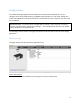
Initial Setup The following steps will help you set up and integrate your mio2 as easily as possible. 1. Connect a Mac or PC to USB Device jack 2, using the supplied USB-A to USB-B cable. mio2 is powered by the the far-right USB Device jack connection, marked “POWER IN.” If you are using only one computer with the mio, always connect it to USB Device Jack 2. 2. Download and install the included iConfig software to a Mac or PC from www.iconnectivity.com/support/downloads. Launch the program.
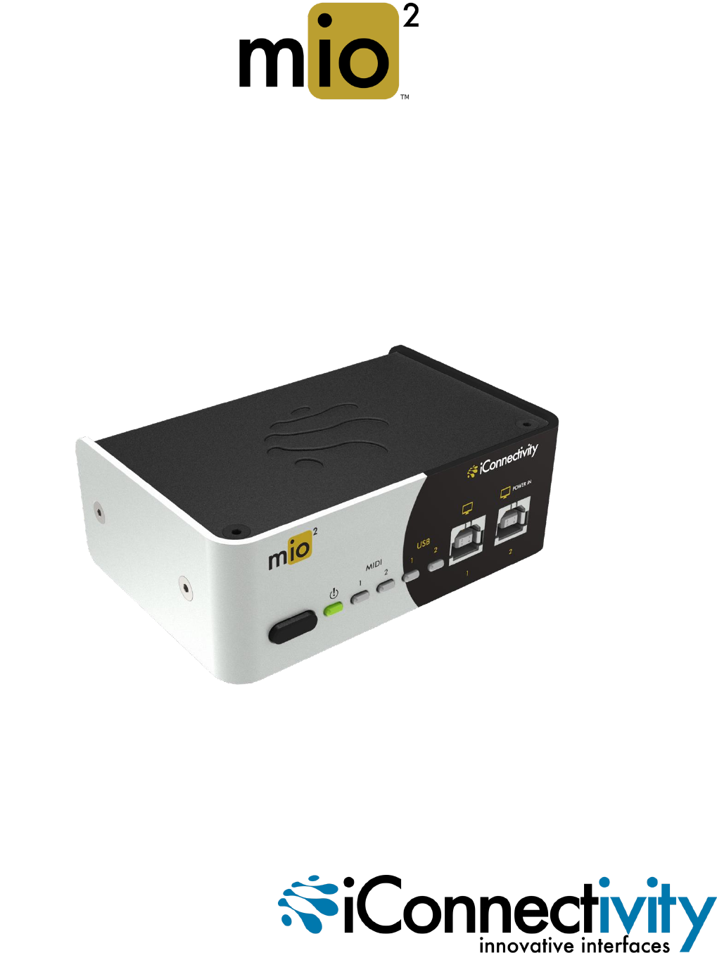
mio2 Hardware Layout 1. Power button - Sleep Mode: Hold for two seconds until green LED goes out, then release. - Wake: Touch button briefly. - Hard-reset: Hold button for seven seconds until all LEDs light up; release button. - Bootloader mode to receive firmware updates: Hold button for four seconds until power LED turns red; release button. MIDI 1 and MIDI2 lights alternate on and off. Press and hold to abort bootloader mode. 3.
mio2 Features The mio2 comes equipped with a powerful suite of features for managing your MIDI interconnections. These are described briefly below, while detailed operating instructions appear in the following pages. Port Routing Each MIDI port on each connection can be routed to any other port. Multiple ports can be merged and routed to a single port. A default routing configuration is loaded in the factory. To view and edit the MIDI port routing, refer to the MIDI Port Routing section.
iConfig Software The included iConfig program looks and works the same on Mac and Windows. Use it to configure all the setup, MIDI routing, and MIDI processing features in your mio2. iConfig also works with additional iConnectivity interfaces connected to the same computer; you only need one installation. IMPORTANT NOTE: To save the mio2’s configuration to memory, select “Device” on the top menu bar, and then select “Save Current Settings”.
Abbreviations and Port Naming The iConfig software uses standard abbreviations for MIDI port names, and the factory-default names reflect the factory-default MIDI routing. These are explained below. USB device jack ports are named based on their default routing connections in the mio2.
MIDI Info Page MIDI Information: Number of MIDI Ports: Shows the total number of MIDI ports available on the 5-pin DIN Jacks and USB Device Jacks. Note: Each MIDI port is a 16-channel data stream. Number of DIN pairs: Shows the number of standard 5-pin MIDI DIN connector pairs (In/Out). Number of Device jacks: Shows the number of USB-B connections available for Mac or PC computer devices. Number of USB MIDI Ports/Device Jack: Each Device Jack can can support multiple MIDI ports.
MIDI Routing and Processing Pages MIDI data is routed from the mio2 inputs to the outputs according to the settings on the MIDI Port Routing Page. The MIDI data can also be manipulated in the mio2 by filtering or remapping functions. These settings are configured in the MIDI Port Filters, MIDI Channel Remap, MIDI Controller Filters, and MIDI Controller Remap pages. Note: MIDI filtering and remapping functions are performed in a specific order on the MIDI inputs and outputs.
MIDI Port Routing Page Every 16-channel MIDI port input from each physical connection can be routed to one or more destinations. For example, a DAW track routed to 5-pin DIN 1 could be routed to an additional DIN jack to layer a synth sound. In the Port Routing example below, MIDI sent to port “DIN 1” from the first computer (on USB Jack 1) is being routed both to the DIN 1 jack and to the other computer's Port 4 (on USB Jack 2).
MIDI Port Filters Page This setting allows specific kinds of MIDI data to be removed (filtered) from each port on either the input or output path. In the Filter Type selection box, choose between Input and Output to select where the filtering is to be applied. Active Sensing and Program Changes are being filtered from the USB 1 / Port “DIN 1” input in the following example.
MIDI Controller Filters Page This setting allows specific MIDI Controller messages to be removed (filtered) on either the input or output path. The list of all 128 controller IDs in the MIDI spec is available, and up to eight different controller filters can be specified. The example below shows Modulation Wheel messages (ID 01) being removed at the input from USB 1 / port “DIN 1,” on MIDI channel 1.
Using mio MIDI Management to Optimize Your Rig The factory setup for your mio2 connects “everything to everything,” so you can quickly get gear connected, use your controllers, and listen to your sounds. Once you have your gear connected and working, and you’ve become familiar with the mio2’s MIDI management features, we recommend you spend some time tweaking your settings to improve efficiency, minimize latency, and avoid potential data loss.
Depending on the loading of your system, the above optimizations can yield a tremendous improvement in data handling and latency. At iConnectivity we like to design smart interfaces that let you build the system you need and ensure the best performance and lowest latency possible. We hope you enjoy your mio-based setup and wish you the best in your creative endeavors.
mio2 Block Diagram 15
Support Email: Support@iConnectivity.