
User's Guide
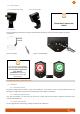
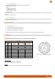


Table Of Contents

6
INSTALLATION TIPS
The housing shape is designed to make the radar placement easier, as well on the horizontal
plan as on the vertical one. Once the radar has been screwed on its bracket, use the line of
sight to point the middle of the detection area (see Figure 4).
The smaller the tilt angle, the longer the radar range, but also the longer the blind zone (the zone without detection just
underneath the radar) :
- α = vertical antenna opening angle (α = 45°)
- β = horizontal antenna opening angle (β = 38°)
- tilt = inclination angle with respect to the horizontal
According to the tune up, the position has to be adapted (see Tune Up procedure for further information).
8 DETECTION ZONE
We have calculated some detections patterns surfaces, based on common installation parameters. Please note that these
values result from theoretic calculations and do not take in account environmental factors.
Figure 6 : dimensions of the lobe according to the installation parameters
Figure 4: line of sight
Figure 5 : angles