
User's Guide
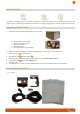
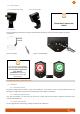

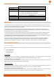
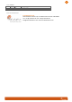
Table Of Contents

5
5.1.4 Self monitoring
The self-monitoring monitors the following parts of the hardware:
- Micro-wavedevice (VCO)
- Mixers
- Analogic format channel
- Analogic/digital converter
- Micro-processor oscillator
- Code running
When a failure is detected, the relays are permanently actuated and the LEDs flashing shows an error code (see further, title
6.2, p. 5).
The radar is reset after 1 hour.
5.1.5 RF channel
This parameter allows to shift the radar’s frequency. If two units face each other, they must be put on different channels, so
they cannot trigger each other.
6 LED indicator
6.1 IN NORMAL OPERATION
• The red LED shows the state of the relay 2.
• The green LED shows the state of the relay 1.
6.2 WHEN THE SELF-MONITORING DETECTS AN ERROR
The two leds blink quickly (2 or 4 quick flashes followed by a 1 sec break, according to the detected error.
7 CABLING
CAUTION :positive security/fail safe relays - contacts given for powered radar.
12 VDC
PIN nr
Color
Power+2 relays*
(NO/NC)
Power + 1 relay
(NO/NC) + RS232*
Power + 2 relays
(NO) + RS232*
1
RED
Power + (DC)
2
BLUE
N/A
N/A
COM relay 2*
3
BLACK
Power - (DCGND)
4
BROWN
NC relay 2*
GND RS232*
GND RS232*
5
WHITE
COM relay 1
COM relay
COM relay 1
6
GREY
NO relay 1
NO relay
NO relay 1
7
YELLOW
NC relay 1
NC relay
NO relay 2*
8
GREEN
COM relay 2*
RX radar (RS232)
*
RX radar (RS232)*
9
PINK
NO relay 2*
TX radar (RS232)*
TX radar (RS232)*
* : RS-232 and relay 2 are and optional features
USER’S OUTPUTS
Resistive load: 110 VAC 0.3A - 24 VDC 0.3A
Inductive load: 110 VAC 0.2A - 24 VDC 0.3A
REMARK
Please disconnect the radar from power before maintenance intervention.
Figure 3 : connector Weipu SP1712/P9