IC-M32-2.qxd 04.1.20 11:06 AM Page A (1,1) New2001 INSTRUCTION MANUAL VHF MARINE TRANSCEIVER iM32 This device complies with Part 15 of the FCC Rules. Operation is subject to the condition that this device does not cause harmful interference.
IC-M32-2.qxd 04.1.20 11:06 AM Page i (1,1) New2001 SAFETY TRAINING INFORMATION Your Icom radio generates RF electromagnetic energy during transmit mode. This radio is designed for and classified as “Occupational Use Only”, meaning it must be used only during the course of employment by individuals aware of the hazards, and the ways to minimize such hazards. This radio is W ARN ING NOT intended for use by the “General Population” in an uncontrolled environment.
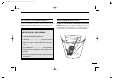
IC-M32-2.qxd 04.1.20 11:06 AM Page ii (1,1) New2001 IN CASE OF EMERGENCY RECOMMENDATION If your vessel requires assistance, contact other vessels and the Coast Guard by sending a distress call on Channel 16. CLEAN THE TRANSCEIVER THOROUGHLY WITH FRESH WATER after exposure to saltwater, and dry it before operation. Otherwise, the transceiver’s keys, switches and controllers may become inoperable due to salt crystallization. ❍ USING CHANNEL 16 DISTRESS CALL PROCEDURE 1. “MAYDAY MAYDAY MAYDAY.” 2.
IC-M32-2.qxd 04.1.20 11:06 AM Page iii (1,1) New2001 FOREWORD FEATURES Thank you for purchasing this Icom product. The IC-M32 VHF MARINE TRANSCEIVER is designed and built with Icom’s state of the art technology and craftsmanship. With proper care this product should provide you with years of trouble-free operation. ☞ Waterproof construction Built tough to withstand the punishing marine environment, the IC-M32 meets JIS waterproof specification grade 7 while using BP-223 (option) or BP-224.
IC-M32-2.qxd 04.1.20 11:06 AM Page iv (1,1) New2001 PRECAUTION RWARNING! NEVER connect the transceiver to an AC outlet. This may pose a fire hazard or result in an electric shock. BE CAREFUL! The transceiver’s right-side panel will become hot when operating continuously for long periods. antenna is closer than 2.5 cm from exposed parts of the body, especially the face or eyes, while transmitting.
IC-M32-2.qxd 04.1.20 11:06 AM Page v (1,1) New2001 TABLE OF CONTENTS SAFETY TRAINING INFORMATION ................................... i IN CASE OF EMERGENCY ............................................... ii RECOMMENDATION .......................................................... ii FOREWORD ...................................................................... iii IMPORTANT ....................................................................... iii EXPLICIT DEFINITIONS .................................
IC-M32-2.qxd 04.1.20 11:06 AM Page 1 (1,1) OPERATING RULES D Priorities • Read all rules and regulations pertaining to priorities and keep an up-to-date copy handy. Safety and distress calls take priority over all others. • You must monitor Channel 16 when you are not operating on another channel. 1 (2) OPERATOR’S LICENSE A restricted Radiotelephone Operator Permit is the license most often held by small vessel radio operators when a radio is not required for safety purposes.
IC-M32-2.qxd 04.1.20 11:06 AM Page 2 (1,1) New2001 2 SUPPLIED ACCESSORIES AND ATTACHMENTS ■ Supplied accessories The following accessories are supplied: Qty. • Flexible antenna . . . . . . . . . . . . . . . . . . . . . . . . . . . . . . . . 1 • Handstrap . . . . . . . . . . . . . . . . . . . . . . . . . . . . . . . . . . . . . 1 • Belt clip (MB-68) . . . . . . . . . . . . . . . . . . . . . . . . . . . . . . . . 1 • Ni-Cd battery pack (BP-224) . . . . . . . . . . . . . . . . . . . . . .
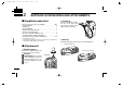
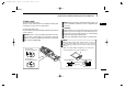
04.1.20 11:06 AM Page 3 (1,1) New2001 SUPPLIED ACCESSORIES AND ATTACHMENTS 2 ï Battery pack To remove the battery pack: Turn the screw counterclockwise, then pull the battery pack in the direction of the arrow as shown below. NOTE: When removing or attaching the battery pack, use a coin or flat-blade screwdriver to loosen or tighten the bottom screw. To attach the battery pack: Insert the battery pack in the IC-M32 completely, then turn the screw clockwise.
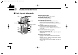
IC-M32-2.qxd 04.1.20 11:06 AM Page 4 (1,1) New2001 3 PANEL DESCRIPTION ■ Front, top and side panels q w q POWER SWITCH [PWR] Push and hold to turn power ON and OFF. w ANTENNA CONNECTOR (p. 2) Connects the supplied antenna. !0 Speaker Microphone Function display (p. 6) o i u e r t y e SCAN/DUAL KEY [SCN•DUAL] • Starts and stops normal or priority scan. (p. 15) • Enters watch mode when pushed for 1 sec. (p. 16) • Exits watch mode when pushed during watch operation. (p.
IC-M32-2.qxd 04.1.20 11:06 AM Page 5 (1,1) New2001 PANEL DESCRIPTION Y]/[Z Z]•[TAG] u CHANNEL UP/DOWN KEYS [Y • Selects an operating channel. (pgs. 8, 9) • Selects the SET mode condition of the item. (p. 17) • Checks tag channels or changes scanning direction during scan. (p. 15) • Sets or clears the displayed channel as a tag (scanned) channel when pushed both keys for 1 sec. (p. 15) • While turning power ON, clears all tag channels in the selected channel group when both keys are pushed. (p.
IC-M32-2.qxd 04.1.20 11:06 AM Page 6 (1,1) New2001 3 PANEL DESCRIPTION ■ Function display q w e r t t LOCK INDICATOR (p. 13) Appears while the lock function is activated. y u i o !8 !7 !0 !6 !1 !2 !5 !4 !3 q TRANSMIT INDICATOR (p. 11) Appears while transmitting. w BUSY INDICATOR Appears when receiving a signal or when the squelch opens. (p. 11) “ ” blinks while monitoring. (p. 13) e TAG CHANNEL INDICATOR (p. 15) Appears when a tag channel is selected. r CALL CHANNEL INDICATOR (p.
IC-M32-2.qxd 04.1.20 11:06 AM Page 7 (1,1) New2001 PANEL DESCRIPTION !1 SQUELCH LEVEL INDICATOR Shows the squelch level. !2 VOLUME LEVEL INDICATOR Shows the volume level. 3 !8 LOW POWER INDICATOR (p. 11) • “LOW” appears when low power is selected. • “LOW” blinks when switching forced low power mode because of a high temperature error or low voltage. 3 !3 VOLUME LEVEL ADJUSTING INDICATOR Blinks while adjusting the volume level.
IC-M32-2.qxd 04.1.20 11:06 AM Page 8 (1,1) New2001 4 BASIC OPERATION ■ Channel selection IMPORTANT!: Prior to using the transceiver for the first time, the battery pack must be fully charged for optimum life and operation. To avoid damage to the transceiver, turn the power OFF while charging. D Channel 16 Channel 16 (Distress channel) is used for establishing initial contact with another station and for emergency communications.
IC-M32-2.qxd 04.1.20 11:06 AM Page 9 (1,1) New2001 BASIC OPERATION 4 D U.S.A., International and Canadian channels D Weather channels There are 57 U.S.A., 57 International, and 61 Canadian channels. These channel groups may be specified for the operating area. There are 10 weather channels. They are used for monitoring weather channels from the NOAA (National Oceanographic and Atmospheric Administration) broadcasts (reception of weather channels possible in USA only).
IC-M32-2.qxd 04.1.20 11:06 AM Page 10 (1,1) New2001 4 BASIC OPERATION ■ Adjusting the volume level ■ Adjusting the squelch level The volume level can be adjusted with [+]/[–]. The IC-M32 has a squelch level adjustment, even though there is no control knob for it. In order to receive signals properly, as well as for the scan to function effectively, the squelch must be adjusted to the proper level. q Push [SQL•MONI], then adjust the squelch level with [+]/[–].
IC-M32-2.qxd 04.1.20 11:06 AM Page 11 (1,1) New2001 BASIC OPERATION 4 ■ Receiving and transmitting CAUTION: Transmitting without an antenna may damage the transceiver. q Push and hold [PWR] to turn power ON. w Set the volume and squelch levels. ➥ Push [SQL•MONI], and push [–] to open the squelch. ➥ Push [SQL•MONI] to stop “SQL” indicator blinking, then push [+]/[–] to set the volume level. ➥ Push [SQL•MONI], and push [+]/[–] to set the squelch level. e Push [Y]/[Z] to select the desired channel.
IC-M32-2.qxd 04.1.20 11:06 AM Page 12 (1,1) New2001 4 BASIC OPERATION ■ Call channel programming The call channel key is used to select Channel 9 by default, however, you can program your most often-used channel in each channel group for quick recall. q Push [CH/WX•U/I/C] for 1 sec. several times to select the desired channel group (USA, INT, CAN) to be programmed. w Push [16•9] for 1 sec. to select the call channel. • “CALL” and call channel number appear. e Push [16•9] again for 3 sec.
IC-M32-2.qxd 04.1.20 11:06 AM Page 13 (1,1) New2001 BASIC OPERATION 4 ■ Lock function ■ Monitor function This function electronically locks all keys (except for [+]/[–], [PTT], [SQL•MONI] and [H/L•LOCK]) to prevent accidental channel changes and function access. The monitor function releases the noise squelch mute. See p. 19 for details of the monitor switch action. ➥ Push [H/L•LOCK] for 1 sec. to turn the lock function ON and OFF. Appears while the lock function is used. LOCK Push for 1 sec.
IC-M32-2.qxd 04.1.20 11:06 AM Page 14 (1,1) New2001 5 SCAN OPERATION ■ Scan types Scanning is an efficient way to locate signals quickly over a wide frequency range. The transceiver has priority scan and normal scan. In addition, the weather alert and auto scan function is available for standby convenience. These functions can be activated simultaneously, depending on the settings in SET mode. (pgs.
IC-M32-2.qxd 04.1.20 11:06 AM Page 15 (1,1) New2001 SCAN OPERATION 5 ■ Setting tag channels ■ Starting a scan For more efficient scanning, add desired channels as tag channels or clear the tag for unwanted channels. Non-tag channels will be skipped during scanning. Tag channels can be assigned to each channel group (USA, INT, CAN) independently. Set the weather alert function, priority scan function, scan resume timer and auto scan function in advance, using SET mode. (pgs.
IC-M32-2.qxd 04.1.20 11:06 AM Page 16 (1,1) New2001 New2001 6 DUALWATCH/TRI-WATCH ■ Description ■ Operation Dualwatch monitors Channel 16 while you are receiving another channel; tri-watch monitors Channel 16 and the call channel while receiving another channel. q Select the desired operating channel. w Push [SCN•DUAL] for 1 sec. to start dualwatch or tri-watch (depending on SET mode setting).
IC-M32-2.qxd 04.1.20 11:06 AM Page 17 (1,1) New2001 SET MODE 7 ■ SET mode programming D SET mode operation SET mode is used to change the condition of 12 transceiver functions: beep tone function, weather alert function, priority scan function, scan resume timer, auto scan function, dual/triwatch function, monitor switch action, automatic backlighting, LCD contrast selection, auto power save function, self check function and battery voltage indicator. q Turn power OFF.
IC-M32-2.qxd 04.1.20 11:06 AM Page 18 (1,1) New2001 7 SET MODE ■ SET mode items D Beep tone function “bP” D Weather alert function “AL” You can select silent operation by turning the beep tones OFF, or you can have 2 types of confirmation beeps sound at the push of a switch. When ON is selected, a fixed beep (Pi) sounds, and when US is selected, the preset beeps (e.g. do, re, mi) sound. An NOAA broadcast station transmits a weather alert tone before any important weather announcements.
IC-M32-2.qxd 04.1.20 11:06 AM Page 19 (1,1) New2001 SET MODE 7 D Scan resume timer “St” D Dual/Tri-watch function “dt” The scan resume timer can be set as a pause (OFF) or timer scan (ON). When OFF is selected, the scan pauses until a received signal disappears. When ON is selected, the scan pauses for 5 sec. after receiving a signal and then resumes even if the signal has been received. This item selects dual or tri-watch as desired. See p. 16 for details.
IC-M32-2.qxd 04.1.20 11:06 AM Page 20 (1,1) New2001 7 SET MODE D Automatic backlighting “bL” D Power save function “PS” This function is convenient for nighttime operation. The automatic backlighting turns the backlighting ON when any key except for [PTT] is pushed. The power save function reduces current drain by deactivating the receiver circuit for preset intervals. • The backlighting is automatically turned OFF after 5 sec. of inactivity. • ON : The power save function is turned ON.
IC-M32-2.qxd 04.1.20 11:06 AM Page 21 (1,1) New2001 SET MODE 7 D Self check function “SC” D Battery voltage indicator “bt” The self check function checks transceiver conditions by itself, and informs you in case a problem is found. The following items are checked after the power is turned ON, then it switches to operation mode. The voltage of the connected battery pack can be turned ON (displayed for 2 sec.) or OFF (non-displayed) after power is turned ON.
IC-M32-2.qxd 04.1.
IC-M32-2.qxd 04.1.20 11:06 AM Page 23 (1,1) BATTERY CHARGING ■ Battery charging ■ Battery caution Prior to using the transceiver for the first time, the battery pack must be fully charged for optimum life and operation. CAUTION! NEVER CAUTION: To avoid damage to the transceiver, turn the power OFF while charging. • Recommended temperature range for charging: +10°C to +40°C (+50°F to +104°F) • Use the specified chargers (BC-150, BC-119N and BC121N). NEVER use another manufacture’s charger.
IC-M32-2.qxd 04.1.20 11:06 AM Page 24 (1,1) New2001 8 BATTERY CHARGING ï Charging connections q Attach the BC-150 to a flat surface, such as a desk or cabin, etc., if desired. w Connect the AC adapter (BC-147A/E or BM-95V) as shown below. e Insert the battery pack with/without the transceiver into the charger. • The charge indicator lights green. DO NOT charge BP-224 more than 12 hours. Otherwise, BP-224 will be damaged. BP-224 must be charged for 8–12 hours only.
IC-M32-2.qxd 04.1.20 11:06 AM Page 25 (1,1) New2001 BATTERY CHARGING 8 ■ Optional battery chargers ï AD-103 installation q Install the AD-103 desktop charger adapter into the holder space of the BC-119N/121N. w Connect the plugs of the BC-119N/121N to the AD-103 desktop charger adapter with the connector, then install the adapter into the charger with the supplied screws.
IC-M32-2.qxd 04.1.20 11:06 AM Page 26 (1,1) New2001 8 BATTERY CHARGING ï Rapid charging with the BC-119N+AD-103 ï Rapid charging with the BC-121N+AD-103 The optional BC-119N provides rapid charging of battery packs. The following are additionally required. • AD-103 charger adapter • An AC adapter (may be supplied with BC-119N depending on version) or the DC power cable (OPC-515L/CP-17L). The optional BC-121N allows up to 6 battery packs to be charged simultaneously.
IC-M32-2.qxd 04.1.20 11:06 AM Page 27 (1,1) SWIVEL BELT CLIP ■ MB-87 contents Qty. q Belt clip ……………………………………………………… 1 w Base clip …………………………………………………… 1 q 9 w Clip the belt clip to a part of your belt and insert the transceiver into the belt clip until the base clip fitting into the groove. w 8 9 ■ To attach q Slide the base clip into the plastic loop on the back of the transceiver as illustrated below. e Once the transceiver is locked in place, it swivels as illustrated below.
IC-M32-2.qxd 04.1.20 11:06 AM Page 28 (1,1) New2001 9 SWIVEL BELT CLIP ■ To detach ➥ Turn the transceiver upside down in the direction of the arrow and pull out from the belt clip. R CAUTION! HOLD THE TRANSCEIVER TIGHTLY, WHEN HANGING OR DETACHING THE TRANSCEIVER FROM THE BELT CLIP. Otherwise the transceiver may not be attached to the holder or swivelled properly if the transceiver is accidentally dropped and the base clip is scratched or damaged.
IC-M32-2.qxd 04.1.20 11:06 AM Page 29 (1,1) TROUBLESHOOTING PROBLEM POSSIBLE CAUSE SOLUTION 10 REF. The transceiver does • The battery is exhausted. not turn ON. • Bad connection to the battery pack. • Recharge the battery pack. • Check the connection to the transceiver. p. 23 p. 3 No sound from speaker. • Squelch level is too deep. • Volume level is too low. • Speaker has been exposed to water. • Set squelch to the threshold point. • Push [+]/[–] to set a suitable level.
IC-M32-2.qxd 04.1.20 11:06 AM Page 30 (1,1) New2001 New2001 11 VHF MARINE CHANNEL LIST Channel number Frequency (MHz) Channel number Frequency (MHz) Channel number Frequency (MHz) Channel number Frequency (MHz) USA INT CAN Transmit Receive USA INT CAN Transmit Receive USA INT CAN Transmit Receive USA INT CAN Transmit Receive 01 01 01A 156.050 160.650 19A 156.050 156.050 20 20A 02 02 156.100 160.700 03 03 156.150 160.750 03A 156.150 156.150 04A 156.200 156.200 05 05A 06 157.
IC-M32-2.qxd 04.1.20 11:06 AM Page 31 (1,1) New2001 SPECIFICATIONS GENERAL • Frequency coverage • Mode • Channel spacing • Power supply requirement • Current drain (at 7.5 V DC) • Frequency stability • Useable temperature range • Dimensions (Projections not included) • Weight (with BP-224) 12 RECEIVER : Transmit 156.025–157.425 MHz Receive 156.050–163.275 MHz : FM (16K0G3E) : 25 kHz : BP-223, BP-224 only : TX High (5 W) 1.5 A typical. Max.
IC-M32-2.qxd 04.1.20 11:06 AM Page 32 (1,1) New2001 New2001 13 OPTIONS D BATTERY CASE AND PACK D DC CABLES • BP-223 BATTERY CASE Battery case for 6 × AA (R6) alkaline cells. • BP-224 Ni-Cd BATTERY PACK 7.2 V/750 mAh Ni-Cd battery pack. • CP-17L CIGARETTE LIGHTER CABLE Allows to charge the battery pack through a 12 V cigarette lighter socket. (For BC-119N) • OPC-515L/OPC-656 DC POWER CABLES Allows to charge the battery pack using 13.8 V power source instead of the AC adapter.
IC-M32-2.qxd 04.1.
IC-M32-2.qxd 04.1.20 11:06 AM Page 34 (1,1) New2001 A-6297D-1EX-w Printed in Japan © 2003–2004 Icom Inc.