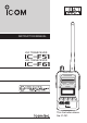
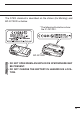
INSTRUCTION MANUAL VHF TRANSCEIVER iF51 UHF TRANSCEIVER iF61 P0 P1 P2 P3 This illustration shows the IC-F51.
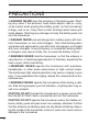
IMPORTANT READ ALL INSTRUCTIONS carefully and completely before using the transceiver. SAVE THIS INSTRUCTION MANUAL— This instruction manual contains important operating instructions for the IC-F51 and IC-F61 uhf transceiver. vhf transceiver This instruction manual includes some functions which are usable only when they are pre-programmed by your dealer. Ask your dealer for details.
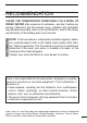
RECOMMENDATION CLEAN THE TRANSCEIVER THOROUGHLY IN A BOWL OF FRESH WATER after exposure to saltwater, and dry it before operating. Otherwise, the transceiver’s keys, switches and controllers may become unusable, due to salt crystallization, and/or the charging terminals of the battery pack may corrode. NOTE: If the transceiver’s waterproof protection appears defective, carefully clean it with a soft, damp (fresh water) cloth, then, dry it before operating.
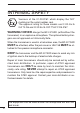
INTRINSIC SAFETY Versions of the IC-F51/F61 which display the “EX” marking on the serial number seal. The approval rating for these models are II 2G Ex ib IIA T3 Gb and II 2D Ex tb IIIC T160°C Db IP67. WARNING! NEVER charge the BP-227AXD (with/without the transceiver) in an explosive atmosphere. The optional battery chargers are not approved as Intrinsically Safe.
The ATEX standard is described on the sticker (Ex Marking) and BP-227AXD as below. * The following illustrations show the IC-F51/F61. BP-227AXD • DO NOT OPEN WHEN AN EXPLOSIVE ATMOSPHERE MAY BE PRESENT. • DO NOT CHARGE THE BATTERY IN HAZARDOUS LOCATION.
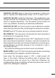
PRECAUTIONS RDANGER! NEVER short the terminals of the battery pack. Shorting may occur if the terminals touch metal objects such as a key, so be careful when placing the battery packs (or the transceiver) in bags, and so on. Carry them so that shorting cannot occur with metal objects. Shorting may damage not only the battery pack, but also the transceiver. RDANGER! NEVER use and charge Icom battery packs with nonIcom transceivers or non-Icom chargers.
CAUTION: DO NOT place or leave the transceiver in direct sunlight or in places with temperatures below –20°C or above +55°C. CAUTION: DO NOT modify the transceiver. The specifications may change and then the transceiver may not comply with the requirements of required regulations. The transceiver warranty does not cover any problems caused by unauthorized modification. CAUTION: DO NOT use harsh solvents such as Benzine or alcohol when cleaning, because they will damage the transceiver surfaces.
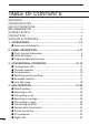
TABLE OF CONTENTS IMPORTANT.......................................................................................... i OPERATING NOTES............................................................................ i EXPLICIT DEFINITIONS....................................................................... i RECOMMENDATION........................................................................... ii INTRINSIC SAFETY.............................................................................iii PRECAUTIONS...
■ Auto emergency transmission................................................... 33 ■ Stun function.............................................................................. 33 ■ BIIS indication............................................................................ 34 ■ Priority A channel selection....................................................... 34 5 BATTERY CHARGING........................................................... 35–44 n Caution....................................................
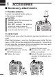
1 ACCESSORIES ■ Accessory attachments D Flexible antenna Connect the supplied flexible antenna to the antenna connector. CAUTION: • NEVER carry the transceiver by holding the antenna. • DO NOT connect the antenna other than listed on page 47. • Transmitting without an antenna may damage the transceiver. ï Jack cover Attach the jack cover when the optional speaker-microphone is not used.
ACCESSORIES 1 ï Battery pack To attach the battery pack: Slide the battery pack on the back of the transceiver in the direction of the arrow (q), then lock it with the battery release button. • Slide the battery pack until the battery release button makes a ‘click’ sound. To remove the battery pack: Push the battery release button in the direction of the arrow (w) as shown below. The battery pack is then removed. OTE: Keep the battery N terminals clean. It’s a good idea to occasionally clean them.
2 PANEL DESCRIPTION ■ Front, top and side panels w e q r Speaker (See the following NOTE.) Microphone Function display (p. 6) i u t y OTE: If the speaker netting (for dust proofing) becomes N wet, dry it with a hair drier (cool mode) etc. before operating the transceiver. Otherwise the audio may be difficult to hear for loss of the sound pressure.
PANEL DESCRIPTION 2 1 q VOLUME CONTROL [VOL] Turns ON the transceiver and adjusts the audio level. w RED BUTTON A desired function can be assigned by your dealer. e ANTENNA CONNECTOR Connects to the supplied antenna. r SPEAKER-MICROPHONE CONNECTOR [SP MIC] Connects to the optional speaker-microphone. (p. 46) 2 3 4 5 6 7 8 [SP MIC] jack cover NOTE: KEEP the [SP MIC] jack cover attached to the transceiver when the speakermicrophone is not used.
2 PANEL DESCRIPTION ■ Front, top and side panels (Continued) u TRANSMIT/BUSY INDICATOR Lights red while transmitting, lights green while receiving a signal, or when the squelch is open. i PTT SWITCH [PTT] Hold down to transmit, release to receive.
PANEL DESCRIPTION 2 ■ Function display q w e 1 r t y 2 u 3 4 i 5 6 q OUTPUT POWER INDICATOR Displayed when Low 2 or Low 1 is selected. 7 8 w AUDIBLE INDICATOR ➥ Displayed when the channel is in the ‘audible’ (unmute) mode. ➥ Displayed when the specified 5-tone/BIIS code is received. 9 e COMPANDER INDICATOR Displayed when the compander function is activated. 11 r KEY LOCK INDICATOR Displayed while the key lock function is ON.
2 PANEL DESCRIPTION ■ Programmable function keys The following functions can be assigned to [P0], [P1], [P2], [P3], [Red], [ ] and [ ] programmable function keys. Consult your Icom dealer or system operator for details concerning your transceivers presetting. CH UP AND DOWN KEYS • Select an operating channel. • Select a transmit code channel after pushing the [TX Code CH Select] keys. •S elect a DTMF channel after pushing the [DTMF Autodial] key.
PANEL DESCRIPTION 2 1 PRIORITY CHANNEL KEYS ➥P ush to select Priority A or Priority B channels. ➥ Hold down [Prio A (Rewrite)] or [Prio B (Rewrite)] for 1 second to rewrite the Priority A or B channel. 2 MR-CH 1/2/3/4 KEYS Directly select an operating channel. 5 MONITOR KEY Independently a one or two of the following functions on each channel: 7 • While holding down, audio is heard (‘Audible’ mode). • Push to mute the channel (‘Inaudible’ mode). • Push to unmute the channel (‘Audible’ mode).
2 PANEL DESCRIPTION C.TONE CHANNEL ENTER KEY Select the continuous tone channel using [CH Up]/[CH Down] keys to change the tone frequency/code setting after pushing this key. TALK AROUND KEY Push to turn the talk around function ON or OFF. • The talk around function equalizes the transmit frequency to the receive frequency for transceiver-to-transceiver communication. WIDE/NARROW KEY Push to toggle the IF bandwidth between wide and narrow. • The wide passband width can be set to 25.0 or 20.
PANEL DESCRIPTION 2 EMERGENCY KEYS ➥ Hold down for preset period of time to transmit an emergency call. ➥ When [Emergency Single (Silent)] or [Emergency Repeat (Silent)] is pushed, an emergency call is transmitted without a beep sound or LCD indication change. • If you want to cancel the emergency call, push (or hold down) the key again before transmitting the call. • The emergency call is transmitted only once or repeatedly until receiving a control code, depending on the presetting.
2 PANEL DESCRIPTION VOICE SCRAMBLER FUNCTION Push to toggle the voice scrambler function ON or OFF. COMPANDER KEY Push to toggle the compander function ON or OFF. The compander function reduces noise components from the transmitting audio to provide clear communication. USER SET MODE KEY ➥ Hold down for 1 second to enter the User Set mode. • During the User Set mode, push this key to select an item that is enabled by your dealer, and push [CH Up]/[CH Down] to change the value or condition.
CONVENTIONAL OPERATION ■ Turning power ON 3 q Rotate [VOL] to turn power ON. w If the transceiver is programmed for a start up passcode, input digit codes as directed by your dealer. 2 3 • The keys in the table below can be used for password input: • T he transceiver detects numbers in the same block as identical. Therefore “01234” and “56789” are the same.
3 CONVENTIONAL OPERATION ■ Call procedure When your system employs tone signalling (excluding CTCSS and DTCS), the call procedure may be necessary prior to voice transmission. The tone signalling employed may be a selective calling system which allows you to call specific station(s) only and prevent unwanted stations from contacting you. q Select the desired TX code channel or 5-tone code according to your System Operator’s instructions. • This may not be necessary depending on programming.
CONVENTIONAL OPERATION 3 ■ Receiving and transmitting 1 NOTE: Transmitting without an antenna may damage the transceiver. See page 1 for antenna attachment. 2 Receiving: q Rotate [VOL] to turn power ON. w Push [ ] or [ ] to select a channel. e When receiving a call, adjust the audio output level to a comfortable listening level. 4 Transmitting: Wait for the channel to become clear to avoid interference. q While holding down [PTT], speak into the microphone at a normal voice level.
3 CONVENTIONAL OPERATION D Transmitting notes • Transmit inhibit function The transceiver has several inhibit functions which restrict transmission under the following conditions: - The channel is in mute condition (‘Inaudible’ condition: “ ” does not appear). - Channel is busy. - Un-matched (or matched) CTCSS is received. - The selected channel is a ‘receive only’ channel.
CONVENTIONAL OPERATION 3 D TX code number edit If the transceiver has [TX Code CH Select] or [TX Code Enter] assigned to it, TX code contents can be edited within the allowable digits. TO EDIT A TX CODE VIA [TX CODE CH SELECT] KEY: q Push [TX Code CH Select] to enter the TX code channel selection mode. • Select the desired channel using [ ]/[ ] if necessary. w Push [TX Code CH Select] for 1 second to enter the TX code edit mode. e Push [TX Code CH Select] to select the desired digit to be edited.
3 CONVENTIONAL OPERATION D DTMF transmission If the transceiver has [DTMF Autodial] assigned to it, the automatic DTMF transmission function is available. Up to 8 DTMF channels are available. TO SELECT A TX CODE: q Push [DTMF Autodial]— a DTMF channel appears. w Push [ ]/[ ] to select the desired DTMF channel. e Push [DTMF Autodial] to transmit the DTMF code in the selected DTMF channel. ■ Scrambler function The voice scrambler function provides private communication between stations.
CONVENTIONAL OPERATION 3 ■ User Set mode 1 If the transceiver has [User Set Mode] assigned to it, you can “customize” the transceiver operation to suit your preferences and operating style. 2 Entering the User Set mode: q Hold down [User Set Mode] for 1 second to enter the User Set mode. w Push [User Set Mode] momentarily to select the appropriate item. Then push [CH Up] or [CH Down] to set the desired level/condition.
4 BIIS OPERATION ■ Default setting The following functions are assigned to each programmable key as the default. Ask your dealer for details. [P0]: Call : Push to transmit a 5-tone/BIIS call when the selected channel is a 5-tone or MSK channel, respectively. [P1]: Digital : Push to select the call list ID/transmit message, or to display the receive message record for selection. [P3]: Moni(Audi) : Push this key after the communication to send a “clear down” signal during MSK channel operation.
BIIS OPERATION 4 ■ Receiving a call 1 D Individual call 2 q When an individual call is received: • Beeps sound. •“ ” is displayed and the mute is released. ”) and the calling • The entered text message (Example: “ station ID (or text) is alternately displayed, depending on the presetting. • “ ” is displayed or blinks, depending on the presetting. 3 4 5 6 7 8 9 10 11 12 Displayed Displayed or blinks w Hold down [PTT], and then speak into the microphone at your normal voice level.
4 BIIS OPERATION D Group call q When a group call is received: • Beeps sound. •“ ” is displayed and the mute is released. • The entered text message (Example: “ ”) and the calling station ID (or text) is alternately displayed, depending on the presetting. • “ ” is displayed or blinks, depending on the presetting. Displayed Displayed or blinks w Hold down [PTT], and then speak into the microphone at your normal voice level. NOTE: Only one station can transmit at a time.
BIIS OPERATION 4 D Displaying the received call record — Queue indication The transceiver memorizes the calling station IDs for a call record. Up to 3 calls can be memorized, and the oldest call record is erased when the 4th call is received. However, once the transceiver is powered OFF, the all records are cleared. q Hold down [P1] (Digital) for 1 second.
4 BIIS OPERATION ■ Transmitting a call There are 3 ways to select a code—selecting the call code from memory, entering the call code from the keypad and calling back from the queue channel record. D Using call memory q While in the standby condition, push [P1] (Digital) to enter the call code memory channel selection mode. Call code text is displayed. w Push [ ]/[ ] to select the desired call code. e Push [P0] (Call) or [PTT]* to call.
BIIS OPERATION 4 1 D Calling back from the queue channel q While in the standby condition, hold down [P1] (Digital) for 1 second to enter queue memory channel selection mode. w Push [ ]/[ ] to select the desired record. 2 3 4 5 6 7 8 e Push [P0] (Call) or [PTT]* to call. *PTT call can be made only when PTT call capability is permitted. OTE: When no answer back is received, the transceiver auN tomatically repeats the call 3 times (default), and “ ” is displayed during each call.
4 BIIS OPERATION D Direct code entry q While in the standby condition, push [TX Code Enter] to enter the TX code edit mode. • Editable code digit blinks. w Push [TX Code Enter] to select the desired digit to be edited. • Editable digit differs according to the setting. e Set the desired digit using [ ]/[ ]/[TX Code CH Up]/[TX Code CH Down]. r Push [TX Code Enter] to set the digit. The editable digit will move to the right automatically. t Repeat e and r to input all allowable digits.
BIIS OPERATION 4 ■ Receiving a message 1 D Receiving a status message 2 q When a status message is received; • Beeps sound. • The calling station ID (or text) and the status message is displayed alternately, depending on the setting. 3 4 5 6 7 8 9 10 11 w Push [P3] (Moni(Audi)) to return to the standby condition. OTE: Only the calling station ID (or text) is displayed (no N message is displayed alternately) when the scroll timer is set to “OFF”.
4 BIIS OPERATION D Receiving an SDM q When an SDM is received; • Beeps sound. • The calling station ID (or text) and the SDM is displayed alternately, depending on the setting. w When the received SDM includes more than 8 characters, the message scrolls automatically, when the automatic scroll function is activated. • Push [Status Up]/[Status Down] to scroll the message manually. e Push [P3] (Moni(Audi)) to return to the standby condition.
BIIS OPERATION 4 D Received message selection The transceiver memorizes the received messages for record. Up to 6 messages for status and SDM, or 95 character SDM’s can be memorized. The oldest message is erased when the 7th message is received. However, once the transceiver is powered OFF, all messages are cleared. q Hold down [P1] (Digital) for 1 second. • Displays queue memory. w Push [P1] (Digital) momentarily. • Displays message memory.
4 BIIS OPERATION ■ Transmitting a status D General The status message can be selected with the programmed text, and the message text is also displayed on the function display of the called station. Up to 24 status types (1 to 24) are available, and the status messages 22 and 24 have designated meanings. Status 22: Emergency* Status 24: GPS request * The status 22 can also be used as a normal status message by disabling the designated meaning. However, the status 24 is fixed.
BIIS OPERATION 4 ■ Transmitting an SDM 1 D General 2 The short data message, SDM, can be sent to an individual station or group stations. Also, 8 SDM memory channels are available and the messages can be edited via PC programming. D Transmitting an SDM q While in the standby condition, push [P1] (Digital), then push [ ]/[ ] to select the desired station/group code. w Push [P1] (Digital) again, then push [ ]/[ ] to select the desired SDM.
4 BIIS OPERATION ■ Position data transmission When the optional OPC-966 interface cable and a GPS receiver is connected to the transceiver, the position (longitude and latitude) data can be transmitted automatically. Ask your dealer or system operator for connection details. The position data is transmitted when; • Status 24 message is received *When the status 24 message, GPS request, is received.
BIIS OPERATION 4 ■ Printer connection 1 When the optional OPC-966 interface cable is connected to the transceiver, a printer can be connected to print out the received SDM content and the ID of the station who sent the message. Ask your dealer or system operator for connection details. 2 ■ PC connection 5 When the optional OPC-966 interface cable is connected to the transceiver, a PC can be connected to provide remote control, data reception, etc.
4 BIIS OPERATION ■ Auto emergency transmission When [Emergency Single (Silent)] or [Emergency Repeat (Silent)] is pushed, an emergency signal is automatically transmitted for the specified time period. The status 22 (Emergency) is sent to the selected ID station, and the position data is transmitted after the emergency signal when a GPS receiver is connected to the transceiver.
BIIS OPERATION 4 ■ BIIS indication 1 The following indicators are displayed for BIIS operation on an MSK channel. 2 : Individual/group call is successful. 3 : Message (status or SDM) transmission is successful. 4 : No answer back is received. 5 : Appears during retry of the call (2nd call). 6 : End the communication. : Operating channel is busy. ■ Priority A channel selection When one of the following operations is performed, the transceiver selects the Priority A channel automatically.
5 BATTERY CHARGING n Caution Misuse of Lithium-ion batteries may result in the following hazards: smoke, fire, or the battery may rupture. Misuse can also cause damage to the battery or degradation of battery performance. WARNING! NEVER charge the battery (with/without the R transceiver) in an explosive atmosphere. The optional battery chargers are not approved as Intrinsically Safe. D Battery caution R DANGER! NEVER strike or otherwise impact the battery pack.
BATTERY CHARGING 5 1 R DANGER! NEVER expose the battery pack to rain, snow, seawater, or any other liquids. Do not charge or use a wet battery pack. If the pack gets wet, be sure to wipe it dry before using. The battery pack itself is not waterproof. 2 R DANGER! NEVER place battery packs near a fire. Fire or heat may cause them to rupture or explode. Dispose of used packs in accordance with local regulations. 5 R DANGER! NEVER solder the battery cell’s terminals, and NEVER modify the battery pack.
5 BATTERY CHARGING ■ Caution D Battery caution (Continued) CAUTION: DO NOT use the battery pack out of the specified temperature range for the transceiver (–20˚C to +55˚C) and the pack itself (–10˚C to +60˚C). Using the pack out of its specified temperature range will reduce it’s performance and the battery cell’s life. Please note that the specified temperature range of the pack may exceed that of the transceiver.
BATTERY CHARGING 5 D Charging caution R DANGER! NEVER charge the battery pack in areas with extremely high temperatures, such as near fires or stoves, inside a sunheated vehicle, or in direct sunlight. In such environments, the safety/protection circuit in the pack will activate and stop the charging. 1 2 3 4 5 R DANGER! NEVER charge the transceiver during a lightning storm. It may result in an electric shock, cause a fire or damage the transceiver. Always disconnect the power adapter before a storm.
5 BATTERY CHARGING ■ Optional battery chargers ï Regular charging with the BC-152N q Attach the BC-152N to a flat surface, such as a desk, if desired. w Connect the power adapter as shown below. e Insert the battery pack with/without the transceiver into the charger. • The charge indicator lights orange. r Charge the battery pack approximately 10 hours, depending on the remaining battery power. • The charge indicator lights green afrer charging is complete.
BATTERY CHARGING 5 1 ❍ Charging indicator: • Lights orange while charging. • Lights green after charging is completed. • Blinks orange or green, or does not light when a problems is detected. SOLUTIONS: • Remove the battery pack, and reinsert it. • Remove the battery pack, clean the battery terminals, then reinsert it. • If the battery pack temperature is high, remove and let it cool down, then reinsert it.
5 BATTERY CHARGING ■ Optional battery chargers (Continued) ï AD-100 installation The AD-100 charger adapter must be installed into the BC-119N or BC-121N before battery charging. q Connect the AD-100 charger adapter and the BC-119N or BC121N. w Install the AD-100 into the holder space of the BC-119N or BC121N with the supplied screws. Plugs AD-100 Sockets Screws supplied with the charger adapter This illustration is described with the BC-119N.
BATTERY CHARGING 5 D Rapid charging with the BC-119N+AD-100 The optional BC-119N provides rapid charging of Li-ion battery pack. The following are additionally required: • One AD-100 (purchase separately) • A power adapter (may be supplied with BC-119N depending on version) or the DC power cable (OPC-515L/CP-23L). Transceiver Turn OFF the power Battery pack 1 2 3 4 5 6 7 8 Power adapter (Not supplied with some versions.) 9 10 11 AD-100 charger adapter is installed in BC-119N.
5 BATTERY CHARGING ■ Optional battery chargers (Continued) D Rapid charging with the BC-121N+AD-100 The optional BC-121N allows up to 6 battery packs to be charged simultaneously. The following are additionally required. • Six AD-100 (purchase separately) • A power adapter (BC-157) or the DC power cable (OPC-656) Transceiver Turn OFF the power Battery pack Power adapter (Purchase separately) AD-100 charger adapters are installed in each slot.
BATTERY CHARGING 5 IMPORTANT: Battery charging caution Ensure the guide tabs on the battery pack are correctly aligned with the guide rails inside the charger adapter. (This illustration shows the BC-152N.
6 SPEAKER-MICROPHONE ■ Optional HM-138 description Alligator type clip To attach the speaker-mic. to your shirt or collar, etc. PTT switch Transmits while pushed Receives while released Microphone Speaker NEVER immerse the connector in water. If the connector becomes wet, be sure to dry it BEFORE attaching it to the transceiver. 45 OTE: The microphone is located at the top of the speaker-miN crophone, as shown in the diagram above.
SPEAKER-MICROPHONE 6 ■ Attachment 1 Attach the connector of the speaker-microphone into the [SP MIC] connector on the transceiver and tighten the screw. 2 3 4 5 6 7 CAUTION: Attach the speaker-microphone’s connector securely to prevent accidental dropping, or water intrusion in the connector. 8 9 10 11 12 IMPORTANT: KEEP the [SP MIC] jack cover attached (transceiver) when the speaker-microphone is not in use.
7 OPTIONS • BP-227AXD li-ion battery pack 7.4 V/1850 mAh/14 Wh Li-ion battery pack. The same as supplied with the transceiver. BP-227AXD must be charged with the optional BC-152N or the BC-119N/121N. • BC-152N desktop charger + BC-147S ac adapter Used for regular charging of the battery pack. The power adapter, BC-147S, must be purchased separately. Charging time: Approximately 9 to 10 hours • BC-119N desktop charger + AD-100 charger adapter + BC-145S ac adapter For rapid charging of battery packs.
OPTIONS 7 Some options may not be available in some countries. Please ask your dealer for details.
8 ATEX CAUTIONS D Special conditions for safe use The equipment is an intrinsically safe equipment. It can be used in a potentially explosive atmosphere. The equipment must be powered only by the battery Icom type BP-227AXD. When the transceiver is used in a hazardous areas, either the jack cover or HM-138 must be attached to the connector. Failure to do this will make the transceiver ATEX non-compliant and may result in an accident during use in hazardous areas.
ATEX CAUTIONS 8 D Meaning of ATEX marking codes 1 2 3 4 Ambient temperature Explosion protection marking 5 CE conformity marking Identification number of notified body (where appropriate) (DEKRA: 0344) 7 Equipment category: 1 (for Zone 0 or 20), 2 (for Zone 1 or 21), 3 (for Zone 2 or 22) Type of Explosive atmosphere: G (for gas, vapors and mist), D (for dusts) Equipment group: (for mines), (for other than mines) Gas Group (see Fig.
51 Aircraft fuel Ethylene Acetylene Hydrogen — Toluene Town Gas (Coal Gas) — Propane — — — — — — Methanol — — — — Carbon Monoxide n-hexane Acetic acid — n-butyl alcohol Heating oil Benzene (pure) Ammonia Ethyl acetate n-butane I-amyl acetate Diesel fuel Ethane Benzine Ethyl alcohol Acetone — T3: 200°C — T2: 300°C Methane T1: 450°C — — — — — — — — — — — — — — — — — — — — Carbon disulphide Ethyl nitrate — — — — — — — — Ethyl ether — — Acetalde h
ABOUT CE AND DOC 9 ereby, Icom Inc. declares that the versions of ICH F51/IC-F61 which have the “CE” symbol on the product, comply with the essential requirements of the Radio Equipment Directive, 2014/53/EU, and the restriction of the use of certain hazardous substances in electrical and electronic equipment Directive, 2011/65/EU. The full text of the EU declaration of conformity is available at the following internet address: http://www.icom.co.
10 INFORMATION ■ Country code list (ISO 3166-1) 1 2 3 4 5 6 7 8 9 10 11 12 13 14 15 16 17 Country Austria Belgium Bulgaria Croatia Czech Republic Cyprus Denmark Estonia Finland France Germany Greece Hungary Iceland Ireland Italy Latvia Codes AT BE BG HR CZ CY DK EE FI FR DE GR HU IS IE IT LV 18 19 20 21 22 23 24 25 26 27 28 29 30 31 32 33 Country Codes Liechtenstein Lithuania Luxembourg Malta Netherlands Norway Poland Portugal Romania Slovakia Slovenia Spain Sweden Switzerland Turkey United Kingdom L
MEMO 1 2 3 4 5 6 7 8 9 10 11 12 13 14 15 16 17 18 19 20
< Intended Country of Use > AT FI IT PL GB RO BE FR LV PT IS TR CY DE LT SK LI HR CZ GR LU SI NO DK HU MT ES CH EE IE NL SE BG A6365H-1EU-19 Printed in Japan © 2005–2017 Icom Inc. Printed on recycled paper with soy ink.