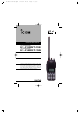
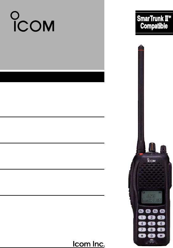
IC-F30G series.qxd 02.1.24 11:29 Page 1 (1,1) INSTRUCTION MANUAL VHF TRANSCEIVER iF30GT/GS UHF TRANSCEIVER iF40GT/GS This device complies with Part 15 of the FCC rules. Operation is subject to the following two conditions: (1) This device may not cause harmful interference, and (2) this device must except any interference received, including interference that may cause undesired operation.
IC-F30G series.qxd 02.1.24 11:29 Page 2 (1,1) SAFETY TRAINING INFORMATION W ARN ING Your Icom radio generates RF electromagnetic energy during transmit mode. This radio is designed for and classified as “Occupational Use Only”, meaning it must be used only during the course of employment by individuals aware of the hazards, and the ways to minimize such hazards. This radio is NOT intended for use by the “General Population” in an uncontrolled environment.
IC-F30G series.qxd 02.1.24 11:29 Page 3 (1,1) this radio by the manufacturer or an antenna specifically authorized by the manufacturer for use with this radio. • DO NOT transmit for more than 50% of total radio use time (“50% duty cycle”). Transmitting more than 50% of the time can cause FCC RF exposure compliance requirements to be exceeded. The radio is transmitting when the “TX indicator” lights red. You can cause the radio to transmit by pressing the “PTT” switch.
IC-F30G series.qxd 02.1.24 11:29 Page 4 (1,1) FOREWORD Thank you for purchasing the IC-F30GT/GS, IC-F40GT/GS FM transceiver. READ ALL INSTRUCTIONS carefully and completely before using the transceiver. SAVE THIS INSTRUCTION MANUAL–This instruction manual contains important operating instructions for the transceiver. INSTALLATION NOTES • When transmitting with a portable radio, hold the radio in a vertical position with its microphone 2.5 to 5 centimeters (1 to 2 in.) away from your mouth.
IC-F30G series.qxd 02.1.24 11:29 Page 5 (1,1) AVOID using or placing the transceiver in direct sunlight or in areas with temperatures below +14°F (–10°C) or above +122°F (+50°C). The basic operations, transmission and reception of the transceiver, are guaranteed within the specified operating temperature range (depending on version). However, the LCD display may not be operate correctly, or show an indication in the case of long hours of operation, or after being placed in extremely cold areas.
IC-F30G series.qxd 02.1.24 11:29 Page 6 (1,1) TABLE OF CONTENTS SAFETY TRAINING INFORMATION . . . . . . . . . . . . . . . . . . . . . . . .i–ii FOREWORD . . . . . . . . . . . . . . . . . . . . . . . . . . . . . . . . . . . . . . . . . . . .iii INSTALLATION NOTES . . . . . . . . . . . . . . . . . . . . . . . . . . . . . . . . . . .iii IMPORTANT . . . . . . . . . . . . . . . . . . . . . . . . . . . . . . . . . . . . . . . . . .iii–iv TABLE OF CONTENTS . . . . . . . . . . . . . . . . . . . . . . . . . . . .
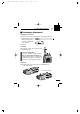
IC-F30G series.qxd 02.1.24 11:29 Page 1 (1,1) ACCESSORIES 1 ‘ Accessory attachment D Supplied accessories The transceiver comes supplied with the following accessories. q Flexible antenna (may q differ from that shown, or may not be supplied with w some versions) w Belt clip D Antenna The antenna screws onto the transceiver as illustrated at right.
IC-F30G series.qxd 02.1.
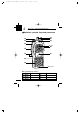
IC-F30G series.qxd 02.1.24 11:29 Page 3 (1,1) PANEL DESCRIPTION 2 q ANTENNA CONNECTOR Connects the supplied antenna. w DEALER-PROGRAMMABLE KEY [F0 (Red)] e DEALER-PROGRAMMABLE KEY [F1 (Black)] r PTT SWITCH [PTT] Push and hold to transmit; release to receive. t DEALER-PROGRAMMABLE KEYS [F2 (Black)], [F3 (Black)] • Push to select the operating channel. Depends on setting. • Can be programmed as [ ✱ ]/[ # ].
IC-F30G series.qxd 02.1.24 11:29 2 Page 4 (1,1) PANEL DESCRIPTION ‘ Function display q o w i e u y r t q SIGNAL STRENGTH METER Indicates relative signal strength level. w BANK NUMBER INDICATOR Indicates operating bank (channel group) number. e LOW POWER INDICATOR Appears when low output power is selected. r MULTI-FUNCTION INDICATOR Indicates operating channel number, channel names, 5-tone code, etc., according to operating condition.
IC-F30G series.qxd 02.1.24 11:29 Page 5 (1,1) 3 BATTERY PACKS ‘ Battery pack replacement Before replacing the battery pack, the volume control MUST be rotated fully counterclockwise, until a click is heard, to turn the power OFF. • Slide the battery release forward, then pull the battery pack upward with the transceiver facing away from you. The BP-210FM only can be used for the intrinsically safe versions.
IC-F30G series.qxd 02.1.24 11:29 3 Page 6 (1,1) BATTERY PACKS ‘ Battery cautions • CAUTION! NEVER short terminals (or charging terminals) of the battery pack. Also, current may flow into nearby metal objects such as a necklace, so be careful when placing battery packs (or the transceiver) in handbags, etc. Simply carrying with or placing near metal objects such as a necklace, etc. causes shorting. This will damage not only the battery pack, but also the transceiver.
IC-F30G series.qxd 02.1.24 11:29 Page 7 (1,1) BATTERY PACKS 3 ‘ Battery charging D Rapid charging with the BC-119N The optional BC-119N provides rapid charging of optional Ni-Cd, Ni-MH and Li-Ion battery packs. The following are additionally required: • One AD-101 (purchase separately). • An AC adapter (may be supplied with the BC-119N depending on version). Turn power OFF.
IC-F30G series.qxd 02.1.24 11:29 3 Page 8 (1,1) BATTERY PACKS D Rapid charging with the BC-121N+AD-101 The optional BC-121N allows up to 6 battery packs to be charged simultaneously. The following are additionally required. • Six AD-101. • An AC adapter (BC-124; must be purchased separately). Turn power OFF. BC-124 (purchased separately) Charge indicator (each indicator functions independently) D Regular charging with Turn power OFF.
IC-F30G series.qxd 02.1.24 11:29 Page 9 (1,1) BATTERY PACKS 3 ‘ Charging NOTE Prior to using the transceiver for the first time, the battery pack must be fully charged for optimum life and operation. • Recommended temperature range for charging: +10°C to +40°C (50°F to 140°F). • Use the supplied charger or optional charger, BC-119N/BC-121N for rapid charging BP-209/210/210FM/211, BC-144 for rapid charging BP-209/210/210FM, BC-137 #11/BC-146 for regular charging BP-209/210/210FM only.
IC-F30G series.qxd 02.1.24 11:29 3 Page 10 (1,1) BATTERY PACKS ‘ Battery case (Option) When using an optional BP-208 BATTERY CASE attached to the transceiver, install 6 AA (R6) size alkaline batteries as illustrated below. D CAUTION • Use ALKALINE batteries only. • Make sure all battery cells are the same brand, type and capacity. • Never mix old and new batteries. Either of the above may cause a fire hazard or damage the transceiver if ignored.
IC-F30G series.qxd 02.1.24 11:29 Page 11 (1,1) PROGRAMMABLE FUNCTIONS 4 ‘ General In the following explanations, programmable function names are bracketed, the specific switch used to activate the function depends on programming. D KEYPAD LOCK FUNCTION This function locks access to all programmable switches (except the switch assigned for the lock function). Push and hold the [Lock] switch for 1 sec. to toggle the lock function ON and OFF. • “ ”appears while the lock function is ON.
IC-F30G series.qxd 02.1.24 11:29 4 Page 12 (1,1) PROGRAMMABLE FUNCTIONS D HIGH/LOW POWER OUTPUT This function selects high or low power for a channel. Push the [High/Low] switch to change transmit output power between high, low1 and low2 power. •“ ” appears when low1 or low2 output power is selected. D SCRAMBLER FUNCTION (optional UT-109 (#02)* or UT-110 (#02)* is required.) This function provides higher communication security. UT-109: Non-rolling type. 32 code numbers are available.
IC-F30G series.qxd 02.1.24 11:29 Page 13 (1,1) PROGRAMMABLE FUNCTIONS 4 D MONITOR AUDIBLE FUNCTION The monitor function allows you to open the transceiver’s squelch manually to check whether a channel is busy or not. The transceiver has 2 conditions for receive standby: Audible condition: This condition mutes audio ONLY when no carrier is present. You can receive (or monitor) any signals on a channel. • Push and hold the [Moni] (LMR) or [Moni (Audi)] (PMR) switch to select the audible condition.
IC-F30G series.qxd 02.1.24 11:29 4 Page 14 (1,1) PROGRAMMABLE FUNCTIONS D DTMF TRANSMISSION This function allows you to send a pre-programmed DTMF code to control a repeater, open another transceiver’s squelch, etc. Manual transmission: Push the desired digit keys in sequence while pushing [PTT]. • Pushing [PTT] may not be necessary depending on programming.
IC-F30G series.qxd 02.1.24 11:29 Page 15 (1,1) PROGRAMMABLE FUNCTIONS 4 D DISPLAY LIGHTING The function display has 3 backlight conditions. ON : Backlight turns ON continuously. OFF : No backlight is available. AUTO : When any key, except [PTT], is pushed, the backlight turns ON for 5 sec. automatically. D SmarTrunk IITM functions This transceiver provides SmarTrunk IITM functions. (Optional UT-105 SmarTrunk II TM Logic Board is required.
IC-F30G series.qxd 02.1.24 11:29 5 Page 16 (1,1) CONVENTIONAL OPERATION ‘ Receiving and transmitting NOTE: Transmitting without an antenna may damage the transceiver. See p. 1 for antenna attachment. Turn power ON as described on p. 3. Receiving: q Push [CH Up]/[CH Down], or rotate [SEL] to select a channel. w Listen for a transmission and adjust [VOL] to a comfortable listening level.
IC-F30G series.qxd 02.1.24 11:29 Page 17 (1,1) CONVENTIONAL OPERATION 5 ‘ Call procedure When your system employs tone signalling (excluding CTCSS and DTCS), the call procedure may be necessary prior to voice transmission. The tone signalling employed may be a selective calling system which allows you to call specific station(s) only and prevent unwanted stations from contacting you. q Select the desired Tx code channel or 5-tone code according to your System Operator’s instructions.
IC-F30G series.qxd 02.1.24 11:29 5 Page 18 (1,1) CONVENTIONAL OPERATION ‘ Tx code channel selection Your radio may be programmed for Tx code channel selection. In this case, you can choose a Tx code channel to be transmitted when using the call function (p. 17). Push [Tx Code CH Up/Down] (assigned to one of the dealer-programmable switches) to select the desired Tx code channel. • The selected code channel (containing a pre-programmed 5-tone code) is transmitted when using the call function.
IC-F30G series.qxd 02.1.24 11:29 Page 19 (1,1) SmarTrunk IITM OPERATION 6 ‘ Basic operation These features are enabled by your Dealer or System operator and may not be available in your system. Contact your Dealer for details. Push the [Bank] switch one or more times to select a channel bank for conventional channels or SmarTrunk II™ channels. • Scanning starts when a channel bank for SmarTrunk IITM is selected.
IC-F30G series.qxd 02.1.24 11:29 6 Page 20 (1,1) SmarTrunk IITM OPERATION D Last number redial*1 Push [M], [M] to automatically redial the last number called. • A high-pitched beep indicates that the number is accepted. D Turbo SpeeDial To automatically dial a commonly used number with one push: • Push one of the turbo SpeeDial keys. D Programming memory speed dial q Push and hold [M] until you hear a high-pitched beep.
IC-F30G series.qxd 02.1.24 11:29 Page 21 (1,1) SmarTrunk IITM OPERATION 6 D Placing a telephone call* Enter the phone number followed by [1], [M]. 2 • A high-pitched beep indicates that the number is accepted. • When the called party answers, push the [PTT] switch to talk, and release it to listen. D Calling another local system subscriber*2 Enter the subscriber number followed by [3], [M]. • A high-pitched beep indicates that the number is accepted.
IC-F30G series.qxd 02.1.24 11:29 7 Page 22 (1,1) OTHER FUNCTIONS ‘ DTMF PAGER/CODE SQUELCH D DTMF pager This function uses DTMF tones for calling and can be used as a “common pager” to inform you that one of your group has called even if the operator is temporarily away from the transceiver. • When the connection code is received, a beep sounds, then “ ” flashes and shows the called station’s code number.
IC-F30G series.qxd 02.1.24 11:29 Page 23 (1,1) OPTIONAL UNIT INSTALLATION 8 You can install two of the following optional units in the transceiver. UT-105 SmarTrunk II Logic Board, UT-109/UT-110 VOICE SCRAMBLER UNIT , UT-111 TRUNKING BOARD, UT-113 MAN DOWN UNIT . TM ‘ Installation q Unscrew nut a, and remove the knobs. w Unscrew screw b, 2 screws c then remove multi-connector cover and rear panel. e Unscrew 2 screws d, then remove multi-connector.
IC-F30G series.qxd 02.1.24 11:29 9 Page 24 (1,1) OPTIONS D BATTERY PACKS/CASE • BP-208 BATTERY CASE Allows a set of Alkaline batteries to operate the handheld when charging rechargeable batteries or in emergencies, etc. 6 AA (R6) alkaline cells are required. • BP-209 Ni-Cd BATTERY PACK 7.2 V/1100 mAh Ni-Cd battery pack, allows more than 7 hours operation. • BP-210/FM Ni-MH BATTERY PACK 7.2 V/1650 mAh Ni-MH battery pack, allows approx. 11 hours operation. BP-210FM for the intrinsicaly safe type.
IC-F30G series.qxd 02.1.24 11:29 Page 25 (1,1) OPTIONS 9 • UT-109 (#02)/UT-110 (#02) SCRAMBLER UNITS Non-rolling type (UT-109)/Rolling type (UT-110) voice scrambler unit provides higher communication security. • UT-111 TRUNKING BOARD Provides LTR® trunking capabilities. • UT-113 MAN DOWN UNIT Provides a measure of safety when working in a hazardous environment, etc. D OTHER OPTIONS • AD-52 EARPHONE JACK ADAPTER Allows you to connect an earphone, 2-conductor 3.5 (d) mm (1⁄8″).
IC-F30G series.qxd 02.1.24 11:29 Page 26 (1,1) INSTRUCTION MANUA A-5668H-1EX-r Printed in Japan © 2000 Icom Inc.