
Install Instructions

Installation, Operation & Application Guide
For more information on our complete range of American-made products – plus wiring diagrams, troubleshooting tips and more, visit us at www.icmcontrols.com
ICM716
ECM to PSC Motor Controller
Once all connections are made, the ICM716 will take the
signal outputs from an X13 or SelecTech constant torque
ECM motor harness and output to a single phase PSC
motor to run the motor. The technician can select a 60, 120
or 180 second off delay by placement of a Jumper on the
Mode of Operation
ICM716 in the desired location (factory default is 180 seconds).
Calls on pins 1 and 2 will activate the LOW speed winding of the PSC motor.
Calls on pin 3 will activate the MEDIUM speed winding of the PSC motor.
Calls on the pins 4 and 5 will activate the HIGH speed windings of the PSC motor.
LIAF283
LED Indicators
• When the LOW LED is illuminated the LOW speed relay is activated and the PSC motor will run at Low speed.
• When the MED LED is illuminated, the Medium speed relay is activated and the PSC motor will run at Medium speed.
• When the HIGH LED is illuminated, the High speed relay is activated and the PSC motor will run at High speed.
• When the DELAY LED is illuminated, the OFF Delay on break (post purge) is activated.
• IF ALL LEDs are OFF, this indicates there are no thermostat calls on pins 1,2,3,4, or 5 and all outputs are OFF.
1. Drill four pilot holes using a #39 (7/64”) drill bit. The 4 hole spacing as
shown in the wiring diagram below.
2. Mount the ICM716 circuit board using four #6 X 3/4” sheet metal screws.
3. Connect the X13/SelecTech harness to the ICM716.
4. Connect the Common wire of the PSC motor (COM) to the COM terminal
of the ICM716 with a ¼” quick connect.
5. Connect the PSC motor wires according to the PSC motor manual to High,
Medium and Low speed terminals on ICM716 with ¼ inch quick connects.
Installation
6. Wire the PSC motor’s capacitor terminals to the appropriate size
capacitor rated for the PSC motor.
7. Supply the 24 VAC “R” to the R terminal of the ICM716 using a ¼”
quick connect if an off delay is desired.
8. Select whether or not you wish to have an off delay of 60, 120 or 180
seconds by placing a jumper in the desired time position and ensuring
R is connected.
DANGER!
Only trained personnel should install or service heating equipment. When working with heating equipment, be sure to read and understand all
precautions in the documentation, on labels, and on tags that accompany the equipment. Failure to follow all safety guidelines may result in
damage to equipment, severe personal injury or death.
CAUTION!
Failure to turn off gas and electric supplies can result in explosion, re, personal injury or death.
Replaces
QwikSwapX3
Specifications
• Motor Voltage: 120 VAC or 208-240 VAC
• Input Control Voltage: 24 VAC
• Input Frequency: 50-60 Hz
• Maximum Blower HP: 1 HP
• Size: 4.95” x 3.95”
ELECTRICAL SHOCK HAZARD – Before installing this unit, turn off power at the main service panel by removing the fuse or
switching the appropriate circuit breaker to the OFF position.
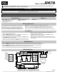
Wiring Diagram
2
3
4
5
1
L
G
N
C
FROM OLD
MOTOR
LOW
COM
HIGH
R
MED
PSC MOTOR OUTPUTS
HIGH
LOW
DELAY
MED
60
120
180
ICM716
C
L
G
N
1
2
3
4
5
X13/SelecTech
Harness
3.95”
COM
LOW
MED
HIGH
CAP
CAP
Capacitor
X13/SelecTech
PSC Motor
Delay 24 VAC
Jumper Selection
4.95”