
Install Instructions

ICM CONTROLS
www.icmcontrols.com 7313 William Barry Blvd., North Syracuse, NY 13212
800.365.5525
LIAF273
A
Optional
cornered
ground on
any of the
phases
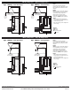
Type 1 Wiring – Fuse Disconnect
BLK
BLK
BLK
Neutral
Bus
WHT
Wire
Nut
ICM530
C
B
Incoming
3-Phase Voltage
Delta Configuration
Ground
Bus
Wiring Diagrams – Delta Configuration
BLK
BLK
BLK
Neutral
Bus
A C
B
WHT
Wire
Nut
Incoming
3-Phase Voltage
Delta Configuration
ICM530
Type 2 Wiring – Circuit Breaker
Optional
cornered
ground on
any of the
phases
Ground Bus
BLK
BLK
BLK
Ground
Bus
Neutral
C
B
A
Ground
Incoming
3-Phase Voltage
Wye Configuration
WHT
ICM530
Neutral
Bus
Type 1 Wiring – Fuse Disconnect
Wiring Diagrams – Wye Configuration
BLK
BLK
BLK
Neutral
C
B
A
Ground
WHT
ICM530
Neutral
Bus
Incoming
3-Phase Voltage
Wye Configuration
Type 2 Wiring – Circuit Breaker
Ground Bus
BLK Black
WHT White
A,B,C Incoming phase
Ground
Legend:
Note 1:
For the ease of checking the SPD
protection status, the LED display should
face outwards after installation has been
complete.
Note 2:
ICM530
is a Type 1 and 2 SPD, designed
to be compatible with 3-phase Delta and
3-phase Wye voltage configuration.
Please check your supply voltage
configuration and voltage levels before
installing the ICM530 per wiring diagram.
Note 3:
• When installing the Surge Protecting
Device (SPD), avoid sharp bends in the
conduit and long line sets.
• Keep the mounting conduit straight and
short in length.