
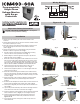
Install Instructions

Important Safety Information
HIGH VOLTAGE WARNING!
– Turn off power
at the main service panel before installing.
Programmable,
Single-Phase
Voltage Monitor
with Surge
Protection
1. Remove cover by extracting the screw from the bottom of the
enclosure.
2. Remove desired size knock-outs from the enclosure needed to install
the required conduits (1/2” or 3/4”).
3. Mount the enclosure to the desired surface with (4) screws and pull
any conduits through the knockouts on the bottom as needed
(refer to Fig. 0).
4. Rest the front panel door in a vertical position using the contactor
bracket as a base of support as seen in Fig. 1.
5. Hold the contactor and unscrew the two Phillips head mounting
screws on the front of the panel also seen in Fig. 1.
6. Whilst holding the contactor against the front panel, lay the front
panel face down as seen in Fig. 2.
7. Rotate the contactor 90 degrees counter clockwise and rest it on its
base as seen in Fig. 3. This orientation will give you access to the
L1, L3 and T1, T3 terminal screws which are needed to mount the
heavy gauge wires of the 60 AMP circuit. CAUTION: DO NOT USE
THE ¼” QUICK CONNECT TERMINALS IN A 60 AMP CIRCUIT.
8. Insert the line wires from the incoming power to the L1 & L3
terminals and tighten down the screws as seen in Fig. 4.
9. Insert the load (equipment) wires to T1 & T3 and tighten down the
screws as seen in Fig. 5.
10. Rotate the contactor 90 degrees clockwise, then rotate the whole
front panel and contactor assembly 180 degrees counter clockwise
so the front panel is facing up and the contactor is resting on its side
as seen in Fig. 6.
11. Adjust the position of the contactor to align the mounting bracket
threaded holes with the front panels through holes also seen
in Fig. 6.
12. Re-insert the two Phillips head screws which secure the contactor to
the front panel and tighten down securely seen again in Fig. 6.
13. Tilt front panel diagonally and insert the panel into the enclosure as
seen in Fig. 7.
14. Lay the front panel horizontally in the enclosure and align the holes
on the sides of the case one at a time also seen in Fig. 7.
15. Using the two larger screws included in the kit, attach the front panel
to the enclosure as seen in Fig. 8, (do not overtighten screws)
16. Close the hinged front plate and secure the upper right corner
into the bracket with the small screw provided in kit as seen in
Figures 9 & 10
17. Once settings have been conFig.ured, attach the top cover and
secure with screw.
Installation
ICM493-60A
control board
Use 75°C Copper wire only
Wiring Diagram
Fig. 0
Fig. 1
Fig. 2
Fig. 4
Fig. 5
Fig. 6
Fig. 7
Fig. 8 Fig. 9 Fig. 10
Fig.ures 0 - 10
Remove
mounting
screws
Align & fasten with screws
Align
hole
Fasten with screw
Fig. 3