
User Guide

• Terminals 4 and 5 are the control signal input terminals
• “Control Mode” is turned ON or OFF in setup
• With “Control Mode” set to “ON,” there must be a voltage present on terminals 4 and
5 for the relay output terminals 1 and 2 to close; this voltage can be supplied from a
thermostat, pressure switch, etc.
• When the voltage on these terminals is re-applied,
the unit will not re-energize until the delay on break
(0-10 minutes) time has elapsed
• Use of terminals 4 and 5 is optional; they will be ignored if the “Control Mode” is
set to “OFF”
• Terminals 1 and 2 are “dry,” normally open contacts
• Terminals1and2areclosedwhenpoweriswithinspecications
• Terminals 1 and 2 open when there is a fault condition
• Terminals 1 and 2 open when there is a loss of the control signal with “Control Mode” set
to “ON”
Note: Terminals 6, 7 and 8 used for ModBus communication on ICM450A PLUS+.
Figure 3
Contactor Voltage
(18-240 VAC)
Optional Control Voltage
Contactor
Coil
COM NO NC
Figure 2
Contactor Voltage
(18-240 VAC)
Optional Control Voltage
Contactor
Coil
COM NO NC
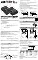
Installation
1. Using (2) #8 screws, mount the ICM450A and ICM450A PLUS+ in a cool, dry, easily
accessible location in the control panel.
2. Connect voltage as shown in Figure 1 (below). Leave existing line and load side
connections intact on the contactor.
3. Load side monitoring is optional (unit may be used to monitor line side only). Wire the
contactor and optional control voltage monitoring as in Figures 2 and 3 (below).
Note: Load/line wire must be rated for 3-phase voltage rating, 20 AWG minimum.
4. Upon application of power, the ICM450A and ICM450A PLUS+ will be on line and will
begin to monitor the system.
Figure 1
Incoming 3-phase
voltage from load
or “back” side of
contactor (optional)
Incoming 3-phase voltage from
line or “front” side of contactor
The incoming 3-phase voltage
is used to power up the
ICM450A as well (190-600)
ICM450A and ICM450A PLUS+ Wiring Diagrams
Load 3
Load 2
Load 1
LOAD
L1 L2
3-Pole Contactor
Load 2
Load 1
L1 L2
2-Pole Contactor
Load
3
LOAD
L3 L3
6 87432 51
Optional Control
Voltage
18-240 VAC
6 87432 51
Optional Control
Voltage
18-240 VAC
ICM450A &
ICM450A PLUS+
Programmable 3-Phase
Line Voltage Monitors
Installation of the ICM450A and ICM450A PLUS+ shall be performed by trained
technicians only. Adhere to all local and national electric codes.
Disconnect all power to the system before making any connections.
Caution
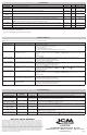
Specification
Input: • Line voltage: Universal, 190-600 VAC
• Frequency: 50-60 Hz
• Control voltage: 18-240 VAC
• Load mide monitoring: Optional
Output: • Type: Relay, SPDT
• Voltage range: 277 VAC @ 10A maximum
Control Operating Temp: • Operating Temperature: -40ºF to +167ºF (-40ºC to +75ºC)
• Storage Temperature: -40ºF to +185ºF (-40ºC to +80ºC)
Mechanical: • Mounting: Surface mount using (2) #8 screws
• Terminations: 1/4” quick connects
• Weight: 12 ounces (341 grams)
ModBus: RS485 Communication (ICM450A PLUS+)
Dimensions: 6.5”L x 4.75”W x 1.09”D
Parameters
Line Voltage: Universal 190-600 VAC
Phase Unbalance Protection : 2-20% adjustable
Over/Under Voltage Protection: • Under Voltage: 2-25% adjustable
• Over Voltage: 2-25% adjustable
Phase Loss Protection: Equals 25% of nominal for any given phase; system will shut
down and a fault will be recorded should this occur
Delay on Break Timer: 0 to 10 minutes adjustable
Control Voltage: 18-240 VAC Control Mode: ON\/OFF
Fault Interrogation Delay: • Time Delay: 0 to 15 seconds adjustable
• Provides a delay between fault detection and system
shutdown - helps to eliminate nuisance trips or unnecessary
shutdowns
Reset Mode: 0 (auto) or 1-10 retries
Set Date and Time: Provides real time clock for date and time stamp (ICM450A PLUS+)
Language: Set to English or Spanish language for display
1. Align the DIN rail mounting plate with the 4 holes on the
back side of the ICM450A/450A Plus+.
2. Thread the four # 10 screws provided in the kit through
the ICM450A/450A Plus+ mounting holes from the top
sideandthreadintothemountingplateasseening5.
** Optional din rail mounting kit sold separately (Order:DIN-ICM450A)
Din Rail Mounting Instructions
Button Functions
Press arrows to scroll
through and select user
parameter settings in
Setup mode. HOLD
down for fast edit.
Press to
enter Setup
mode and
select user
parameters.
Hold for
voltage display
a b, b c,
a c
(simultaneously).
Press to read
faults. Hold for 5
seconds to clear
faults and reset
memory.
Voltage Read Calibration
Hold down both the UP & Down buttons simultaneously to enter calibration mode (Fault
andSetupLEDswillash).PresstheUp&Downbuttonsindividuallytoadjustdisplay
voltage allowing a few seconds between presses for voltage averaging. Press SETUP to
exit calibration
1. Press the SETUP button to enter Setup mode. Setup LED will light.
2. Use the and arrows to change user parameters.
3. Scroll through setup by pressing and releasing the SETUP button.
4. When the last parameter has been set, the phase average will be displayed and the
Setup LED will automatically turn OFF.
Setting the Parameters
Terminating the Resistor
ICM450APlus Models
RS485 terminating resistor
Enabled = Installed
Disable = Not Installed
6 87432 51
MODBUS Data Mapping QR Code
To Access the MODBUS data mapping tables, SCAN the
QR Bar code to the right.