
User Guide

SE
24
VAC
120
VAC
ILK
BLW
TIME
90
120
160
45
SW1
OFF
OFF
ON
ON
SW2
ON
OFF
OFF
ON
OFF-ON
O
N
1 2
1 2
Thermostat
IND
CAP
L2
L1
L1
L2
Junction
Box
Fuse Disconnect
or Circuit
Breaker
P1
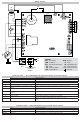
LEGEND
SEC Secondary
COM Common
EAC Electronic Air Cleaner
M1 Park
ILK Interlock Switch
IND Inducer Motor
BLW Blower
F1 Fuse
SE Spark Electrode
P1 9-Pin Connector
PC3 5-Pin Connector
Ground
BB1007
Wiring Diagram
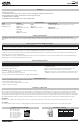
Fault Code Table –– Green LED Displays the Operational Status of the Control Board
Fault Trouble shooting tips
LED ON
Normal operation, no call for heat Normal
Fast Flash
Call for heat Normal operation with a heat call
OFF
No power Install power, check fuse box or circuit breaker
1
Ignition Failure (after 3 tries and start of soft lockout) Check all safeties, check all grounds, check flame sensor, and insure gas valve is turned on.
2
Pressure switch failed to close within 30 seconds of
inducer
Check for obstructions in the Pressure switch tube or a faulty pressure switch
3
Limit switch failed open Check for faulty limit switch or limit switch wires. Also, check any safety in series with the limit
switch.
4
Pressure switch stuck closed before inducer blower is
energized
Check for faulty pressure switch.
5
Gas Valve fault detected Check for proper gas pressure, check wiring to the gas valve, check gas valve operation.
6
Brownout Voltage Check the primary supply line voltage with respect to ground.
Check to see if anything is loading down the line voltage to the control.
Rapid
Wrong polarity of 120 VAC and Neutral. Check the line voltage with respect to ground and neutral with respect to ground for proper
polarity.
Fault Code Table –– Yellow LED displays the operational status of Flame.
Fault Trouble shooting tips
LED ON
Flame is sensed Normal operation
Slow Flash
Weak Flame Clean or replace flame sensor and check flame sense ground
Fast Flash
Flame fault Check or replace flame sensor and check flame sense ground