
User Guide

7313 William Barry Blvd.
North Syracuse, NY 13212
800.365.5525
LII382
ICM
2907
Direct Spark Ignition Board
Install New Control
1. Ground yourself. When handling circuit board, hold it by the edges.
2. Fasten circuit board with retaining screws.
3. Connect all line voltage, low voltage, and accessory wires.
4. Verify the sequence of operation.
Safety Considerations
Only trained personnel should install or service heating equipment. When working with heating equipment, be sure to read and understand all precautions in the
documentation, on labels, and on tags that accompany the equipment. Failure to follow all safety guidelines may result in damage to equipment, severe personal injury or
death.
Electrostatic Discharge (ESD) Precautions
CAUTION!
Use caution when installing and servicing the furnace to avoid and control electrostatic discharge; ESD can impact electronic components. These precautions must be followed to
prevent electrostatic discharge from hand tools and personnel. Following the precautions will protect the control from ESD by discharging static electricity buildup to ground.
1. Disconnect all power to the furnace. Do not touch the control or the wiring prior to discharging your body’s electrostatic charge to ground.
2. To ground yourself, touch your hand and tools to a clean, metal (unpainted) furnace surface near the control board.
3. Service the furnace after touching the chassis. Your body will recharge with static electricity as you shuffle your feet or move around, and you must reground yourself.
4. Reground yourself if you touch ungrounded items.
5. Before handling a new control, reground yourself; this will protect the control. Store used and new controls in separate containers before touching ungrounded objects.
6. ESD damage can also be prevented by using an ESD service kit.
• Direct Spark Ignition (DSI) control board
• Microprocessor-based
• Controls inducer motor, blower motor, electronic air cleaner (if equipped), spark ignitor and the gas valves
• Monitors timing, trial for ignition, system switches, flame sensing and lockout
• Compatible with LP or natural gas
• LED indication for status and fault codes to aid in troubleshooting
Features
CAUTION!
To service control, and prior to disconnection, label all wires. Failure to do so may result in wiring errors that can cause dangerous operation.
Remove Existing Control
1. Turn thermostat to OFF position or set it to the lowest possible setting.
2. Turn OFF electrical supply to furnace.
3. Turn OFF gas supply to furnace.
CAUTION: Failure to turn off gas and electric supplies can result in explosion,
fire, death, or personal injury.
4. Remove furnace blower and control access doors.
5. Disconnect thermostat wires and humidifier wires (if equipped with a humidifier).
6. Disconnect line voltage, blower, electronic air cleaner wires (if equipped),
and transformer wires.
7. Remove screws and any other fasteners, and the old circuit board.
8. Examine control and control box to check for water stains.
9. Make repairs if any sources of water leakage are found. Be sure to check
humidifiers, evaporator coils, and vent systems in the area of the control.
Heat Mode:
Upon a call for heat from the thermostat, the control board checks to see if the limit switch is closed and the pressure switch is open. If the limit switch is closed and the
pressure switch is open, the circuit board energizes the draft inducer motor and waits for the pressure switch to close. When the pressure switch is proven closed, the
control board energizes the draft inducer motor for a 20 second pre-purge time. Following the pre-purge, the board energizes the spark ignitor and main gas valves and the
draft inducer motor remains energized. Once the flame has been proven, the blower turns on after a 30 second delay. If the call for heat is removed after successful ignition,
the circuit board will de-energize the gas valves and run the draft inducer motor for 45 seconds. The blower turns off after the user settable blower purge time delay.
Fan Mode:
If the thermostat is calling for fan, the blower turns on after a 1 second delay. If the call for fan is removed, the control board turns off the blower after 1 second.
Cool Mode:
In cool mode, the blower turns on after a 7 second delay. When cooling is satisfied, the control board turns the blower off after a 90 second post purge delay.
Summary of Operation
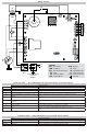
P1 Pin Connections Out Pins DIP Switch Settings
BLOWER PURGE TIMING
Time SWITCH 1 SWITCH 2
90 OFF ON
120 OFF OFF
160 ON OFF
45 ON ON
OFF-ON
O
N
1 2
1 2
Pin 1 n/a
Pin 2 Gas valve ground
Pin 3 Limit switch (W)
Pin 4 Gas valve outputs
Pin 5 Pressure switch output
Pin 6 Pressure switch input
Pin 7 Flame sense input
Pin 8 Limit switch output
Pin 9 Flame ground
P1
Specifications
Input
Voltage: 18-30 VAC
Frequency: 60 Hz
Outputs
Inducer blower
Type: Relay
Rating: 1/6 HP @125 VAC
Gas Valves
Type: Relay
Rating: 1A @ 24 VAC
Blower
Type: Relay
Rating: 1/4 HP @125 VAC
Environmental
Operating Temperature: -40°F to 165°F (-40°C to 74°C)
Mechanical
Dimensions: 14.5” x 5”
Replaces: Reznor 195265