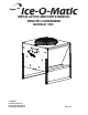
INSTALLATION AND PARTS MANUAL REMOTE CONDENSERS MODELS: VRC Ice-O-Matic 11100 East 45th Ave Denver, Colorado 80239 Part Number 9081245-01 Date 3/08
*
Remote Condenser Introduction How To Use This Manual Ice-O-Matic provides this manual as an aid to the service technician in installation and maintenance of remote condensers. Do not attempt to perform installation, start-up or maintenance unless you have read and fully understand this manual. If, at any time, you encounter conditions that are not addressed in this manual, call, E-mail or write the Ice-O-Matic Service Department: Ice-O-Matic 11100 E. 45th Ave. Denver, Co.
Remote Condenser Table of Contents Introduction Page i Table of Contents Page ii Freight Claim Procedure Page iii Warranty Page iv General Information Page 1 Installation Guidelines Page 2 Remote Refrigeration System Page 4 Component Description Page 5 Installation Page 6 Service Parts VRC Page 10 Page ii
Remote Condenser Freight Claim Procedure Freight Claims Important! Inspect Promptly This merchandise has been carefully inspected and packed in accordance with the carrier’s packing specifications. Responsibility for safe delivery has been assumed by the carrier. If loss or damage occurs, you as the consignee must file a claim with the carrier and hold the container for carrier’s inspection.
Remote Condenser Warranty Ice-O-Matic Parts and Labor Domestic & International Limited Warranty Mile High Equipment LLC (the “Company”) warrants Ice-O-Matic brand ice machines, ice dispensers, remote condensers, water filters, and ice storage bins to the end customer against defects in material and factory workmanship for the following: • Cube ice machines,”GEM” model compressed ice machines ,” MFI” model flake ice machines and remote condensers.
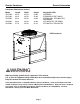
Remote Condenser General Information Condenser Dimensions (Inches) Model VRC1001 VRC1061 VRC2061 Length 29.18 29.18 29.18 Width 29.50 29.50 29.50 Height 38.90 38.90 38.90 VRC2661 VRC5061 29.18 37.78 29.50 29.50 38.90 38.76 Compatible With: ICE0500R4 ICE0605/6R4, EMF1106R2 ICE0805/6/R3, ICE1005/6/7R3, EMF2306R2 ICE1405/6/7R3, ICE1506R3 ICE1806/7R3, ICE2106/7R3 VRC Condenser Note the warning symbol where it appears in this manual.
Remote Condenser General Information Introduction Ice-O-Matic Remote Condenser Systems are comprised of three components. The pre-charged remote condenser, the pre-charged ice maker and the pre-charged line set. The pre-charged line sets are available in 25, 40, 45, 60 or 75 foot line set lengths. The 60 foot line set will require adding an additional 16 ounces of refrigerant to the system. The 75 foot line set will require adding an additional 28 ounces of refrigerant to the system.
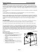
Remote Condenser General Information The VRC remote condensers incorporate the mixing valve in the condenser. This configuration allows up to a 100 foot calculated remote line set run. Reference the diagram below to calculate the maximum 100 foot line set run. Limitations for new remote machines that have the mixing valve mounted in the condenser. Maximum Rise is 35 feet. Maximum Drop is 15 feet. Maximum equivalent run is 100 feet. Formula for figuring maximum equivalent run is as follows: Rise x 1.
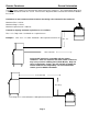
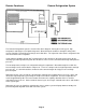
Remote Condenser Remote Refrigeration System The Remote Refrigeration System is shown in the above diagram. During the freezing cycle, high temperature and high pressure liquid refrigerant is directed from the condenser through a mixing valve, receiver, liquid line solenoid heat exchanger and a filter drier. The expansion valve meters refrigerant to the coils on the back of the evaporator.
Remote Condenser Component Description Mixing Valve (Headmaster, Low Ambient Control Valve) This valve serves as the head pressure regulating valve. It contains a pre-determined charge of nitrogen in the valve bellows. When the temperature at the condenser is above 70°F (21°C), the refrigerant flow from the compressor is directed by the mixing valve through the condenser and into the receiver.
Remote Condenser Installation Electrical Connections 1. The icemaker and the remote condenser both require a solid earth ground that meets National, State and Local Codes. 2. Reference the ice machine and condenser date plate for current requirements to determine wire size for electrical hook up. 3. Make sure the supply voltage is the same as the rated voltage shown on the nameplate. 4. Reference wiring diagram below for proper connections.
Remote Condenser Installation Support Leg Installation-VRC 1. After removal of the packaging and fasteners, lift the condenser assembly off of the skid. 2. Locate the legs and leg braces attached to the condenser assembly. Cut the wire ties and separate the legs from the condenser. 3. Locate the fasteners that are in a bag attached to the condenser top panel. 4. Assemble the legs and braces to the condenser as shown below.
Remote Condenser Installation Vertical Air Flow Page 8
Remote Condenser Installation Proper Tubing Routing When installing the discharge and liquid lines from the remote condenser to the icemaker, please use the following guidelines: 1. The remote condenser (#2) should always be installed above the icemaker (#4) as shown with a vertical air flow on page 8. 2. All excess tubing (#1) should be routed inside the building and coiled in a vertical spiral as shown (3#) on page 8, to prevent oil trapping in the lines.
Remote Condenser Item Description Service Parts VRC1001 VRC1061 VRC2061 VRC2661 VRC5061 1 Fan Guard 9131452-01 9131452-01 9131452-01 9131452-01 9131460-01 2 Top Panel 3013222-01 3013222-01 3013222-01 3013222-01 3013303-01 3 ¼-20 x 1/2 Screw 9031019-04 9031019-04 9031019-04 9031019-04 9031019-04 4 Fan Blade 9131451-01 9131451-01 9131451-01 9131451-01 9131461-01 5 Fan Motor 9161117-02 9161117-01 9161117-01 9161117-01 9161118-01 6 ¼-20 x ¾ Cap Screw 9031001-02 90310
Remote Condenser Service Parts Page 11