SERVICE AND INSTALLATION MANUAL MFI Series Ice-O-Matic 11100 East 45th Ave Denver, Colorado 80239 Part Number 9081358-01 17-3168-01 Date 10/08
MFI Series Introduction How To Use This Manual Ice-O-Matic provides this manual as an aid to the end user and service technician in installation and maintenance of the MFI Series ice machines. Do not attempt to perform installation, start-up or maintenance unless you have read and fully understand this manual. If, at any time, you encounter conditions that are not addressed in this manual, call, E-mail or write the Ice-O-Matic Service Department: Ice-O-Matic 11100 E. 45th Ave. Denver, Co.
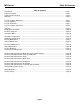
MFI Series Table Of Contents Table of Contents Introduction .................................................................................................................................. Table Of Contents........................................................................................................................ Freight Claim Procedure.............................................................................................................. Warranty ......................................
MFI Series Freight Claim Procedure Important! Inspect Promptly This merchandise has been carefully inspected and packed in accordance with the carrier’s packing specifications. Responsibility for safe delivery has been assumed by the carrier. If loss or damage occurs, you as the consignee must file a claim with the carrier and hold the container for carrier’s inspection.
MFI Series Warranty Ice-O-Matic Parts and Labor Domestic & International Limited Warranty Mile High Equipment LLC (the “Company”) warrants Ice-O-Matic brand ice machines, ice dispensers, remote condensers, water filters, and ice storage bins to the end customer against defects in material and factory workmanship for the following: • Cube ice machines,”GEM” model compressed ice machines ,” MFI” model flake ice machines and remote condensers.
MFI Series For the Installer Installation Guidelines: For proper operation of the Ice-O-Matic ice machine, the following installation guidelines must be followed. Failure to do so may result in loss of production capacity, premature part failures, and may void all warranties. Ambient Operating Temperatures: Minimum Operating Temperature: 50°F (10°C) Maximum Operating Temperature 100°F (38°C) Note: Ice-O-Matic ice makers and dispensers are not approved for outdoor installation.
MFI Series For The Installer Page 2
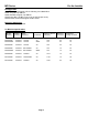
MFI Series For the Installer Bin Application The MFI Series is designed to fit the following Ice-O-Matic Bins. ●B42, using Bin Top KBT 24 ●B25, B40 B55 using Bin Top KBT19. ●B100 using Bin Top KBT 23 (one unit) or KBT 22 (two units). ●B120, B150, B170-Not designed for MFI Series. Dispenser Application Flaked ice is not dispensable. Ice Machine Specifications Model Number WxDxH (Inches) Basic Electrical Condenser Minimum Circuit Ampacity Maximum Fuse Size Refrigerant Charge oz.
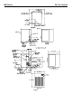
MFI Series For the Installer Location: Ice-O-Matic ice machines are designed to be installed indoors in a controlled environment. Install the ice machine in a location where it has enough space around it to be accessible for service. A minimum of 6 inches must be allowed at the back for air circulation on air cooled models. Try to avoid hot, dirty and crowded locations. Be sure that the location of the machine is within the environmental limitations. Storage Bin: Remove the bin packaging.
MFI Series For the Installer Allow 6 “Clearance for Air Circulation Allow 6 “Clearance for Air Circulation A proper installation locates the ice machine indoors, but in a place where the heat and noise it produces are not objectionable. Two Units on One Bin Air cooled machines discharge hot air out the back and must have a minimum of 6 inches of clearance behind the ice machine. Space for maintenance access is also important.
MFI Series For the Plumber Water Inlet: ●Air Cooled Models: The recommended water supply is clean, cold water. Use 3/8 inch O.D. copper tubing, connect to the 3/8 inch male flare at the back of the cabinet. Install a hand valve near the machine to control the water supply. ●Water Cooled Models: A separate 3/8 inch O.D. copper line is recommended, with a separate hand valve to control it. Connect to the 3/8 inch FPT condenser inlet at the back of the cabinet.
MFI Series For the Electrician Electrical Connections: Check the ice machine nameplate (located on the back panel) for the voltage requirements, and minimum circuit ampacity. The ice machine requires a solid chassis to earth ground. Connect the ice machine to its own electrical circuit so it is individually fused. Voltage variation must remain within the limitations, even under starting conditions. Note: All external wiring must conform to national, state and local electrical codes.
MFI Series For the Installer Final Check List: _______1. Is the ice machine installed indoors in a location where the air and water temperatures are controlled and where they do not exceed the design limitations? _____2. Is there an electrical service disconnect within sight of the installed machine? _____3. Has the voltage been checked and compared to the nameplate requirements? _____4. Have all the plumbing connections been made and checked for leaks? _____5.
MFI Series Start Up Pre-Start Inspection: 1. Remove the front and side service panels. 2. Check that any shipping blocks have been removed. 3. Inspect the interior of the ice machine for loose screws or wires. 4. Check that no refrigerant lines are rubbing each other. 5. Check that the fan blades turn freely (Air Cooled). 6. Check that the unit is installed correctly according to the final check list on page 8. Start Up: 1. Go through the pre-start inspection. 2.
MFI Series Component Description ●Control Box: Contains the electrical controls that operate the machine. ●High Pressure Cut Out Switch: An auto-reset switch sensing the high side refrigeration pressure. It will shut the machine off if the discharge pressure exceeds 450 psig. ●Low Pressure Cut Out Switch: An auto-reset switch sensing the low side refrigeration pressure. It will disconnect power to the circuit board and shut down the machine if the low pressure falls too low.
MFI Series Component Description ●Contactor: A definite purpose contactor connecting the compressor and the fan motor to the power supply. ●Circuit Board: Controls the operation of the ice machine using input from the sensors and pressure controls. Switches loads on and off thru relays. (Reference Photo Below) ●Potential Relay: The compressor start relay. ●Mode (ON/OFF) Switch: Manual control for the machine.
MFI Series Component Description ●Evaporator: A refrigerated vertical tube filled with water and containing a water seal and auger. ●Auger: A solid stainless steel double spiral auger, it pushes the ice crystals up to the top of the evaporator. ●Water Seal: A two part “face” seal, the top half rotating with the auger, the bottom half stationary, the sealing action being where the two “faces” meet. ●Ice Sweep: A plastic cap with “fingers”. It revolves with the auger to “sweep” the ice into the ice chute.
MFI Series Electrical Sequence Electrical Sequence: There are 7 indicator lights on the control board: ●WTR-OK: (Water OK) Green. Normal=Glowing. Glow when there is water in the reservoir. ●PWR-OK: (Power OK) Green. Normal=Glowing. Glows when the power board has power and is functional. ●Service: Red. Normally Off. ●Freeze: Red. Normally glowing when making ice. ●Bin Full: Red. Normally Off when making ice. ●LED1: White. Located next to the Control Board’s Compressor Relay.
MFI Series Operation: Water Water enters the machine through the 3/8 inch male flare at the rear of the cabinet, goes to the water reservoir which it enters through the float valve. The water then goes out the bottom of the reservoir tank to the bottom of the evaporator. Reservoir overflow or evaporator condensation is routed to the drain. Water cooled models have a separate water circuit for the cooling water.
MFI Series Operation: Performance Beginning at the compressor, the refrigerant is compressed into a high temperature gas. The discharge line directs this gas to the condenser. At the condenser (air or water cooled) the gas is cooled by either air or water and then it condenses into a liquid. This high pressure liquid then goes through the liquid line to the expansion valve.
MFI Series Sanitizing and Cleaning It is the USER’S RESPONSIBILITY to keep the ice machine and ice storage bin in a sanitary condition. Without human intervention, sanitation will not be maintained. Ice machines also require occasional cleaning of their water systems with a specifically designed chemical. That chemical dissolves mineral build up that forms during the ice making process.
MFI Series Bearing Maintenance Bearing Maintenance: The bearing in the breaker should also be checked at least two (2) times per year. Switch the machine OFF and check the bearing. 1. Remove the chute cover. 2. Unscrew the ice sweep 3. Removing the water shed and unscrewing the breaker cover. Note: Left Hand Threads 5. Inspect the bearing. There should be plenty of grease in sight. If grease is needed the bearing and breaker should be removed to check the action of the bearing.
MFI Series Sensor Maintenance Bin Control Sensor: The bin control uses devices that sense light, therefore they must be kept clean enough so that they can “see”. Slide Bin Controls to Remove At least twice a year, remove the bin control sensors from the base of the chute, and wipe the inside clean, as illustrated. Water Sensor: The ice machine uses a probe in the water reservoir to determine if there is water.
MFI Series Maintenance: Air Cooled Clean the air cooled condenser: Air flow on this model is from front to back, so the inside of the ice machine will have to be available to clean the air cooled condenser. Use a vacuum cleaner or coil cleaner if needed. DO NOT use a wire brush. ● Disconnect electrical power, and remove the air filter if applicable. The filter may be cleaned or replaced. ● Clean the condenser: the condenser may appear to be clean on the surface, but it can still be clogged internally.
MFI Series Auger Maintenance Auger: In some areas, the water supply to the ice machine will contain a high concentration of minerals, and that will result in an evaporator and auger becoming coated with these minerals, requiring a more frequent removal than twice per year. If in doubt about the condition of the evaporator and auger, the auger can be removed so the parts can be inspected. Note: Water filters can filter out suspended solids, but not dissolved solids.
MFI Series Service Diagnosis Symptom Possible Cause Probable Correction No ice is made nothing operates. •Unit off due to no power •Restore Power •Unit off due to master switch in OFF position •Switch master Switch to ON •Unit off due to low water level •Check water supply, filter strainer, float valve. Correct water supply. •Unit off due to ice level sensors. (Photo Eyes ) blocked. •Check/clean ice level sensors. •Unit off due to scale on water level sensor. •Clean water level sensor.
MFI Series Service Diagnosis Symptom Possible Cause Probable Correction Unit makes ice, but very slowly •High discharge pressure because of a dirty condenser. •Clean filter and condenser. •Low capacity because the auger and evaporator are coated with mineral scale. •Clean the water system. •Low suction pressure due to low refrigerant charge. •Locate leak. Recover the refrigerant, repair leak, replace drier, evacuate and weigh in the nameplate charge. •Drain plugged up. •Clean out drain.
MFI Series Control System Diagnostics The Control System consists of: ●Control Board ●Water Sensors ●Ice Sensors ●High Pressure Cut Out ●Low Pressure Cut Out If the unit is OFF, check the control board: 1. Is the Power OK light on? If not check power to the unit. If it has power, and the Power OK light is not on, check the high pressure and low pressure cut outs. If they are both closed, replace the board. If the POWER OK light is ON, go to the next step. 2.
MFI Series R&R- Water Reservoir, Bin Control Water Reservoir: 1. Disconnect electrical power supply. 2. Shut off water supply to the ice maker. 3. Remove the front panel. 4. Disconnect water inlet tube from reservoir inlet fitting. 5. To remove float valve, push in “locking tabs” as shown and pull float up. Note: The plunger/seat is available separately as a part. 6. To remove reservoir, pull up and remove water sensor. 7. Disconnect water outlet tubes. 8.
MFI Series R&R-Bearing and Breaker Note: Removal of the auger, water seal, evaporator and gear motor must begin at the top of the assembly. To Remove the Breaker Bearing Assembly: 1. Disconnect electrical power. 2. Remove panels. 3. Push back bail clamp and remove ice chute cover. 4. Unscrew and remove ice sweep. 5. Lift up and remove ice chute. 6. The breaker may be removed from the auger and evaporator without disturbing the auger. a. Unscrew breaker cover from breaker (Note: Left Hand Threads) b.
MFI Series R&R-Auger To Remove the Auger: 1. Disconnect electrical power. 2. Turn off the water to the machine. 3. Unclip the evaporator drain hose, pull it down and drain the evaporator into the bin or container. 4. Remove the top panel. 5. Swing bail clip down and remove the ice chute cover. 6. Unscrew ice sweep. 7. Remove ice chute body. 8. The auger and breaker/bearing may now be removed as an assembly. a. Unscrew four (4) Allen head cap screws holding breaker to evaporator. b.
MFI Series R&R-Water Seal To Remove the Water Seal: (Assuming all steps to remove the auger have been performed) 1. The gear motor/evaporator assembly will have to be exposed. 2. Remove the four (4) hex head cap screws holding the evaporator to the gear motor assembly. Lift the evaporator up and off the gear motor. 3. Remove the snap ring or wire retainer from the groove under the water seal. 4. Pull or drive out the lower half of the water seal.
MFI Series R&R-Evaporator To Replace the Evaporator: (Assuming all steps for removal of the thrust bearing, breaker, auger and water seal have been performed). 1. Recover the refrigerant from the ice machine. 2. Unsweat the refrigerant connections: a. At the thermostatic expansion valve outlet. b. At the suction line at the joint about three (3) inches from the evaporator. 3. Remove the evaporator. 4. Unsweat the drier from the liquid line. 5.
MFI Series R&R-Gear Motor To Check the Gear Motor: 1. Remove wires from terminals 1 and 2 2. Use an ohmeter to check for continuity. If there is none, replace only the motor. If there is continuity but the motor will not start, check the motor’s start switch. 3. Remove motor end bell or motor stator. With ohmeter wires attached to 1 and 2 move centrifugal switch actuator up and down to simulate motor rotation. If the ohmeter does not show any change, replace the switch or motor.
MFI Series R&R-Fan Blade and Motor To Remove the Condenser Fan Motor Assembly: 1. Disconnect electrical power to the ice machine 2. Remove top panel and the service panels. 3. Unplug the fan motor wire leadsfrom the fan motors. 4. Remove the two (2)head bolt from the top end of the fan motor assembly. (Fig 1) 5. Lift up the fan motors and bracket assembly about ½ inch and pull out the fan assembly out the right service access hole. (Fig 2) 6. Repair as needed. 7.
MFI Series Refrigeration System Service Refrigeration Service: General: This ice machine uses R404A refrigerant and polyolester oil. Do NOT use mineral oil in this refrigeration system. ●When the refrigeration system is serviced, a special liquid line drier is required. It is included with replacement compressor. ●R404A is not compatible with mineral oil so these ice machines use Polyolester oil. Polyolester oil absorbs water very easily.
MFI Series MFI0500 Wiring Diagram Wiring Diagram MFI0500 Air, MFI0500 Water Page 32
MFI Series MFI0800 Wiring Diagram Wiring Diagram MFI0800 Air, MFI0806 Air, MFI0806 Water W/BK Page 33
MFI Series MFI0805/1255 Wiring Diagram Wiring Diagram MFI0805, MFI1255 Air Page 34
MFI Series MFI1256 Wiring Diagram Wiring Diagram MFI1256 Air Page 35
MFI Series Service History What to Do Before Calling for Service: ●Check the water supply to the ice machine. The ice machine is designed to shut off if there is no water to it. Check the water filters if there are any. ●Check the power supply to the ice machine. Reset the breaker if it is tripped. ●If both water and power have been checked and are available, try switching the power OFF and then ON. After 2 minutes the machine should restart.