
Service Manual
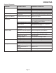
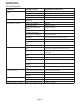
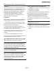
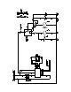
Table Of Contents
- Table of Contents
- Specifications Page 2
- General Information And Installation Page 3
- Water Supply And Drain Connections Page 4
- Final Check List Page 5
- Operating Instructions Page 6
- Operational Checks Page 7
- Component Description Page 8
- Operation - Electrical Sequence Page 9
- Freeze Cycle Page 10
- Cleaning Switch Page 11
- Service Diagnosis Page 12
- Service Diagnosis Page 13
- Maintenance And Cleaning Instructions Page 14
- Cleaning Water System Page 15

Operation - Electrical Sequence
The following charts illustrate which switches and
components are ON or OFF during the two phases
of the icemaking cycle.
Refer to the wiring diagram for reference.
FREEZING CYCLE
Electrical components ON OFF
Compressor •
Water Pump •
Fan Motor •
Hot Gas Valve •
Inlet Water Valve •
Electrical Controls CLOSE OPEN
Evaporator Thermostat (contacts 3-4) •
Evaporator Thermostat (contacts 3-2) •
Bin Thermostat •
HARVEST CYCLE
Electrical components ON OFF
Compressor •
Water Pump •
Fan Motor (Air cooled only) •
Hot Gas Valve •
Inlet Water Valve •
Electrical Controls CLOSE OPEN
Evaporator Thermostat (contacts 3-4) •
Evaporator Thermostat (contacts 3-2) •
Bin Thermostat •
ICEU070A
Page 9