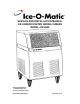
SERVICE AND INSTALLATION MANUAL ICE UNDERCOUNTER SERIES CUBERS MODEL-ICEU060 Mile High Equipment 11100 East 45th Ave Denver, Colorado 80239 Part Number 9081291-01 Print Date 11/01
Introduction ICEU060 To the owner or user: This product manual is a source of information about the installation, start up, cleaning, maintenance, and repair of the product.
Specifications ICEU060 Specifications: Model Number ICEU060 24 Hour Capacity 55 lbs. Operating Requirements: Air Temperature Water Temperature Water Pressure Voltage Bin Storage Capacity 28 lbs. Basic Electrical 115/60/1 Minimum 50° F 40° F 20 PSIG 103.5 V Maximum Fuse Size 15 Ref Type. Ounces R134a, 9.5 oz Maximum 100° F 100° F 100 PSIG 126.5 V Ice-O-Matic ice machines are not designed for outdoor installations. Machine requires voltage indicated on rating nameplate.
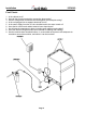
Installation ICEU060 Location: Prior consideration for the location of the ice machine shall include: Installation location to be indoors with a minimum room temperature of 50°F and with a maximum room temperature of 100°F. The incoming water temperature to the machine should be between 40°F and 100°F. Service Access. Allow enough space at the rear of the cabinet for the utility connections. Allow enough space for the machine to be pulled out from its installed location.
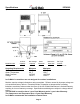
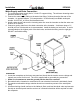
Installation ICEU060 Water Supply and Drain Connection: 1. The recommend water supply line is ¼ inch O.D. copper tubing. The minimum incoming water pressure should be 20 psig. 2. Connect the water supply tubing to the water inlet fitting (3/4 hose thread) at the rear of the icemaker. An optional adapter (1/4 compression x ¾ hose thread) is available under part number 1011337-43, or from a local hardware store 3.
Installation ICEU060 Final Check: 1. 2. 3. 4. 5. 6. 7. 8. 9.
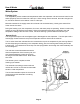
Initial Start Up ICEU060 1. 2. 3. 4. Open the water supply valve. Move electrical breaker or switch to the ON position. Remove the front panel. Check the cube size control shaft, it should be in a preset position. If not, rotate the control shaft clockwise until the unit comes on. Note: Cube size adjustments may be required. Start with the shaft in the “mid” position. 5. The machine will go through a “dry cycle”; this will take about 10 minutes. The water fill and harvest cycle will begin. 6.
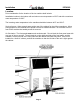
How It Works ICEU060 Component Description Cube Size Control The Cube size control is located in the front of the control box, behind the front panel. The sensing capillary tube of the cube size control is routed out of the control box into its bulb holder on the evaporator coil. It is a reverse acting temperature control with double throw contacts. Turning its knob all the way counterclockwise also shuts off the icemaker.
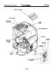
Component Location ICEU060 Page 8
How It Works ICEU060 Water System Freezing Cycle The refrigeration process creates cold temperatures within the evaporator coils and removes heat from the water sprayed up into the inverted ice cube cups. When enough heat is removed, the water changes into ice, and forms where it is the coldest: in the ice cube cups. Minerals contained in the supply water will not freeze and are drained away. Mostly pure water will be frozen into the ice cubes.
How It Works ICEU060 Refrigeration System Freezing Cycle The ice cubes are formed in an inverted mold that is refrigerated. The refrigeration process begins at the compressor. There, refrigerant vapor is compressed and flows from the compressor through the discharge line as a high temperature, high pressure gas. In the discharge line there is a strainer with two outlets; one leads to the condenser, and the other one to the hot gas valve.
How It Works ICEU060 Refrigeration System Harvest Cycle (When the cubes are released) The ice cubes have been formed in an inverted mold that was refrigerated. Now the refrigeration system will change to warm the cube mold and release the cubes. The process begins at the compressor. There, refrigerant vapor is compressed and flows from the compressor through the discharge line as a high temperature, high pressure gas. Before the gas gets to the condenser, it goes through a strainer.
Operation and Adjustment ICEU060 The information shown below covers a wide range of air and water temperatures. It is intended as a guideline only, and is based on data compiled from NEW Clean units. Allow a variation from each end of the range given.
Sanitizing And Cleaning ICEU060 An Ice-O-Matic ice machine represents a sizable investment of time and money in any company’s business. In order to receive the best return for that investment, it MUST receive periodic maintenance. It is the USER’S RESPONSIBILITY to see that the unit is properly maintained. The following is a list of recommended maintenance that will help keep the machine running with a minimum of problems. Maintenance and cleaning should be scheduled at least every six (6) months.
Service Diagnosis ICEU060 SYMPTOM Unit will not run. POSSIBLE CAUSE Blown fuse or breaker. Compressor cyles intermittenly. Low voltage. Dirty condenser. Restricted air circulation. Non condensibles in system. Cubes too small. Cloudy cubes. Irregular size cubes, Some cloudy. Cubes too large. Decreased ice capacity. Low ice capacity. Poor harvest. No harvest. Excessive water in ice storage bin. Cube size control too warm. Partially restricted cap tube. Moisture in system. Overcharged. Undercharged.
Component Replacement ICEU060 Bin Thermostat 1. Unplug the icemaker to disconnect electrical power. 2. Remove screws and cabinet front panel. 3. Remove screws and the control box cover, disconnect electrical wires from the bin thermostat control. 4. Dismount the bin thermostat from the control box. 5. Remove the rear panel. 6. Pull the bin thermostat capillary line from the tube in the ice storage bin. Remove complete control from ice machine. 7. Replace with a new control in reverse order of removal.
Component Replacement ICEU060 Spray Platform 1. Unplug the icemaker to disconnect electrical power. 2. Open ice bin door. 3. Pull out on the left side and remove curtain assembly. 4. Lift the spray platform up and pull out to get to the water hose at the base of the platform. 5. Pull hose off of connection to spray platform, and pull platform from the icemaker. 6. To replace, reverse the removal procedures. Inlet Water Valve 1. Unplug the icemaker to disconnect electrical power. 2.
Component Layout ICEU060 Page 17
Wiring Diagram ICEU060 Page 18