
Owner's Manual

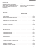
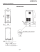
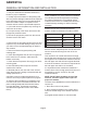
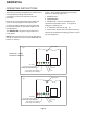
Table Of Contents
- Table of Contents
- SPECIFICATIONS Page 2
- CABINET DIAGRAMS Page 3
- GENERAL INFORMATION AND INSTALLATION Page 4
- ELECTRICAL CONNECTIONS Page 5
- WATER SUPPLY AND DRAIN CONNECTIONS Page 6
- FINAL CHECK LIST Page 7
- OPERATING INSTRUCTIONS Page 8
- INITIAL START UP CONTINUED Page 9
- SETTING THE DISPENSING SELECTOR Page 11
- PRINCIPLE OF OPERATION Page 12
- REFRIGERANT CIRCUIT Page 13
- MECHANICAL SYSTEM Page 14
- COMPONENT DESCRIPTION Page 15
- COMPONENT DESCRIPTION Page 16
- COMPONENT DESCRIPTION Page 17
- COMPONENT DESCRIPTION Page 18
- SERVICE DIAGNOSIS Page 19
- SERVICE DIAGNOSIS Page 20
- MAINTENANCE AND CLEANING INSTRUCTION Page 21
- CLEANING INSTRUCTIONS OF WATER SYSTEM Page 22
- REMOVAL AND REPLACEMENT Page 23
- TOP BEARING REPLACEMENT Page 24
- BEARING REPLACEMENT - CONTINUED Page 25
- WATER SEAL Page 26

ELECTRICAL CONNECTIONS
See data plate for current requirements to
determine wire size to be used for electrical
connections. All Ice-O-Matic ice machines require
a solid earth wire. This Ice-O-Matic ice machine is
supplied from the factory completely pre-wired and
only needs to be plugged into a nearby 115 volt
outlet.
Make sure that the ice machine is connected to its
own circuit and individually fused (see data plate
for fuse size).
The maximum allowable voltage variation should
not exceed -10% and +10% of the data plate
rating. Low voltage can cause faulty functioning
and may be responsible for serious damage to the
overload switch and motor windings.
NOTE: All external wiring should conform to
national, state and local standards and regulations.
Check voltage on the line and the ice machine’s
data plate before connecting the unit.
GEMD270A
Page 5