
Owner's Manual
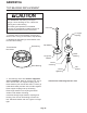
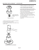
Table Of Contents
- Table of Contents
- SPECIFICATIONS Page 2
- CABINET DIAGRAMS Page 3
- GENERAL INFORMATION AND INSTALLATION Page 4
- ELECTRICAL CONNECTIONS Page 5
- WATER SUPPLY AND DRAIN CONNECTIONS Page 6
- FINAL CHECK LIST Page 7
- OPERATING INSTRUCTIONS Page 8
- INITIAL START UP CONTINUED Page 9
- SETTING THE DISPENSING SELECTOR Page 11
- PRINCIPLE OF OPERATION Page 12
- REFRIGERANT CIRCUIT Page 13
- MECHANICAL SYSTEM Page 14
- COMPONENT DESCRIPTION Page 15
- COMPONENT DESCRIPTION Page 16
- COMPONENT DESCRIPTION Page 17
- COMPONENT DESCRIPTION Page 18
- SERVICE DIAGNOSIS Page 19
- SERVICE DIAGNOSIS Page 20
- MAINTENANCE AND CLEANING INSTRUCTION Page 21
- CLEANING INSTRUCTIONS OF WATER SYSTEM Page 22
- REMOVAL AND REPLACEMENT Page 23
- TOP BEARING REPLACEMENT Page 24
- BEARING REPLACEMENT - CONTINUED Page 25
- WATER SEAL Page 26

REMOVAL AND REPLACEMENT
Bearings, Auger, Water Seal
Note: Metric tools are required for this procedure.
Disconnect electrical power.
1. Remove all panels and the sink assembly.
2. Remove the spout cover.
3. Use a 17mm socket to remove the top bolt
holding the ice sweep to the auger.
4. Use a 13mm socket to remove the four bolts
holding the breaker to the auger.
5. Lift up to remove breaker.
To remove top bearing:
6. Remove snap ring from the top of the breaker.
7. Turn breaker over and using a ¾” punch or bolt,
tap the bearing out from the bottom.
To remove auger:
8. After removing breaker, pull up on the auger to
remove it.
To remove water seal or bottom bearing.
9. Remove bin cover.
10. Disconnect drain and water line from bin.
11. Remove nut holding bin to chassis.
12. Pull bin out of machine.
13. Remove screws holding air deflector to chassis
and pull deflector out of the unit.
14. Remove screws holding reservoir to bulkhead
panel.
15. Remove screws holding bulkhead panel to
chassis frame, push panel back several inches.
16. Use a 13 mm open end or box wrench and
remove the three bolts holding the adapter stand to
the evaporator.
17. Lift evaporator up and off the stand.
18. Tap water seal and bottom bearing out of the
evaporator from the top down.
To remove gear reducer.
1. Disconnect power leads and sensor wires from
motor.
2. Perform steps to remove bottom bearing.
3. Use a 10 mm socket or box wrench to remove
the 5 bolts holding the gear reducer to the unit.
4. Remove the gear reducer from the unit.
Reverse all individual sections to reassemble
that section except for the top bearing and
water seal. See the next page.
GEMD270A
Page 23