
Owner's Manual
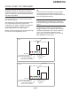
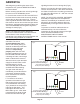
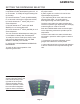
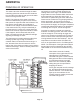
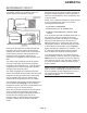
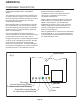
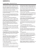
Table Of Contents
- Table of Contents
- SPECIFICATIONS Page 2
- CABINET DIAGRAMS Page 3
- GENERAL INFORMATION AND INSTALLATION Page 4
- ELECTRICAL CONNECTIONS Page 5
- WATER SUPPLY AND DRAIN CONNECTIONS Page 6
- FINAL CHECK LIST Page 7
- OPERATING INSTRUCTIONS Page 8
- INITIAL START UP CONTINUED Page 9
- SETTING THE DISPENSING SELECTOR Page 11
- PRINCIPLE OF OPERATION Page 12
- REFRIGERANT CIRCUIT Page 13
- MECHANICAL SYSTEM Page 14
- COMPONENT DESCRIPTION Page 15
- COMPONENT DESCRIPTION Page 16
- COMPONENT DESCRIPTION Page 17
- COMPONENT DESCRIPTION Page 18
- SERVICE DIAGNOSIS Page 19
- SERVICE DIAGNOSIS Page 20
- MAINTENANCE AND CLEANING INSTRUCTION Page 21
- CLEANING INSTRUCTIONS OF WATER SYSTEM Page 22
- REMOVAL AND REPLACEMENT Page 23
- TOP BEARING REPLACEMENT Page 24
- BEARING REPLACEMENT - CONTINUED Page 25
- WATER SEAL Page 26

MECHANICAL SYSTEM
The mechanical system of the Ice-O-Matic Ice
Dispenser consists of a gear motor assembly that
drives (through a ratchet coupling) a worn shaft or
auger placed on its vertical axis within the freezing
cylinder.
The gear motor is made of a single-phase electric
motor with a permanent capacitor. This motor is
directly fitted in the gear case through which it
drives – in a counter clockwise rotation at a speed
of 9.5 rpm – the freezer auger linked to it by the
ratchet coupling.
NOTE If the gear motor rotates in the wrong
direction (counter-clockwise) or is not rotating at all
the unit will stop immediately and the 3RD
WARNING YELLOW LED will turn on showing the
intervention of the Electromagnetic Safety Device -
based on Hall Effect principle.
After diagnosing and eliminating the source of the
failure, restart the unit by pressing the RESET
button or turn the power switch OFF and ON (Fig.
7).
The RED LED will start blinking and after 3
minutes the ice machine will resume normal
operations by running first the gear motor and then
the compressor.
When the gear motor rotating speed is slowed
below 1300 rpm - normal speed is 1400 rpm - the
Electromagnetic Safety Device transmits an
electrical signal to the MICROPROCESSOR to
stop the unit operation immediately (just as it does
for the wrong rotation) and the 3rd YELLOW
WARNING LED turns on. This is done to avoid
overloading the electrical and mechanical
components of the entire Drive System and extend
their durability.
NOTE: After diagnosing and eliminating the source
of the gear motor slow rotation, restart the unit by
pushing the RESET button to or turning the power
line main switch OFF and ON.
NOTE: Any time the machine stops with a problem
the front 4 LED’s start to blink.
REFRIGERANT METERING DEVICE:
·
Capillary tube
OPERATING PRESSURES
(With 70°F ambient temperature)
·
Discharge pressure: 130 to 145 psig
·
Suction pressure: 14.5 psig
·
REFRIGERANT CHARGE (R134 A): 13 oz.
NOTE: Before charging the refrigerant system
always check the type of refrigerant and quantity
as specified on the individual ice machine data
plate.
The refrigerant charges indicated are relatives to
averages operating conditions.
GEMD270A
Page 14
Fig 7
Bin full
Bin empty
Reset button
No water
Power
Hi cond temp when Steady
3 minute wait when Blinking
Auger Motor when Steady
Hi evap temp when Blinking