
Owner's Manual
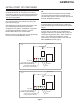
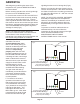
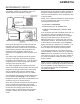
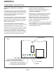
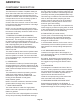
Table Of Contents
- Table of Contents
- SPECIFICATIONS Page 2
- CABINET DIAGRAMS Page 3
- GENERAL INFORMATION AND INSTALLATION Page 4
- ELECTRICAL CONNECTIONS Page 5
- WATER SUPPLY AND DRAIN CONNECTIONS Page 6
- FINAL CHECK LIST Page 7
- OPERATING INSTRUCTIONS Page 8
- INITIAL START UP CONTINUED Page 9
- SETTING THE DISPENSING SELECTOR Page 11
- PRINCIPLE OF OPERATION Page 12
- REFRIGERANT CIRCUIT Page 13
- MECHANICAL SYSTEM Page 14
- COMPONENT DESCRIPTION Page 15
- COMPONENT DESCRIPTION Page 16
- COMPONENT DESCRIPTION Page 17
- COMPONENT DESCRIPTION Page 18
- SERVICE DIAGNOSIS Page 19
- SERVICE DIAGNOSIS Page 20
- MAINTENANCE AND CLEANING INSTRUCTION Page 21
- CLEANING INSTRUCTIONS OF WATER SYSTEM Page 22
- REMOVAL AND REPLACEMENT Page 23
- TOP BEARING REPLACEMENT Page 24
- BEARING REPLACEMENT - CONTINUED Page 25
- WATER SEAL Page 26

INITIAL START UP CONTINUED
NOTE: If the evaporating temperature has not
dropped lower than 30° F within ten minutes of
compressor start-up, the evaporating temperature
sensor will detect the abnormal temperature and
stop the unit operation.
In this circumstance, the 3rd warning YELLOW
LED will blink (Fig.3).
After diagnosing and eliminating the cause of the
poor evaporating temperature (insufficient
refrigerant in the system, inoperative compressor
or inoperative evaporator sensor), push the
RESET BUTTON on the control board.
Before resuming operation the unit will go through
the usual 3 minute STAND-BY period.
OPERATION CHECKS UPON THE UNIT START
UP
D. Remove the service panels and (if needed)
connect the refrigerant service gauges to the
corresponding service valves to check both the HI
and LO refrigerant pressures.
NOTE:The condenser temperature sensor, which
is located within the condenser fins, keeps the
head (condensing) pressure between two preset
valves.
If proper flow of cooling are is prevented by a
clogged condenser or inoperative fan motor, the
condenser temperature rises. When it reaches
158° F the condenser temperature sensor
shuts-off the ice machine and turns on the 2nd
RED WARNING LIGHT (Fig.4).
GEMD270A
Page 9
Fig 3
Bin full
Bin empty
Reset button
No water
Power
Hi cond temp when Steady
3 minute wait when Blinking
Auger Motor when Steady
Hi evap temp when Blinking
Fig 4
Bin full
Bin empty
Reset button
No water
Power
Hi cond temp when Steady
3 minute wait when Blinking
Auger Motor when Steady
Hi evap temp when Blinking