SERVICE AND INSTALLATION MANUAL PEARL ICE® / WATER DISPENSER MODEL-GEMD270A Ice-O-Matic 11100 East 45th Ave Denver, Colorado 80239 Part Number 9081407-01 Print Date 9/09
SERVICE PARTS MANUAL 22 INCH WIDE ICE SERIES CUBERS MODEL-ICE0320, ICE0520 Includes 50Hz.
GEMD270A INTRODUCTION This manual provides the specifications and the step-by-step procedures for the installation, start-up, operation, maintenance and cleaning for the Ice-O-Matic GEMD270A counter top Pearl Iceâ dispenser. NOTE: To retain the safety and performance built into this ice machine, it is important that installation and maintenance be conducted in the manner outlined in this manual. Ice-O-Matic 11100 East 45th Ave.
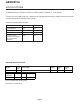
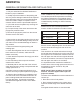
GEMD270A SPECIFICATIONS GEMD270A: Ice Maker Dispenser, TouchFree, 200 lb ice making capacity, Pearl Ice â, 12 lb storage To keep your Ice-O-Matic Pearl Ice â Dispenser at peak performance levels, periodic maintenance checks must be carried out as indicated in this manual.
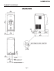
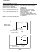
GEMD270A CABINET DIAGRAMS Page 3
GEMD270A GENERAL INFORMATION AND INSTALLATION LOCATION AND LEVELING UNPACKING AND INSPECTION 1. Call your authorized Ice-O-Matic Distributor or Dealer for proper installation. 2. Visually inspect the exterior of the packing and skid. Any severe damage noted should be reported to the delivering carrier and a concealed damage claim form filled in subject to inspection of the contents with the carrier’s representative present. 3. a) Cut and remove the plastic strip securing the carton box to the skid.
GEMD270A ELECTRICAL CONNECTIONS See data plate for current requirements to determine wire size to be used for electrical connections. All Ice-O-Matic ice machines require a solid earth wire. This Ice-O-Matic ice machine is supplied from the factory completely pre-wired and only needs to be plugged into a nearby 115 volt outlet. Make sure that the ice machine is connected to its own circuit and individually fused (see data plate for fuse size).
GEMD270A WATER SUPPLY AND DRAIN CONNECTIONS GENERAL WATER DRAIN When choosing the water supply for the ice flaker, consideration should be given to: The recommended drain tube is a copper, rigid plastic or reinforced flexible tubing (supplied) with .75" (19mm) I.D. which runs to an open trapped and vented drain. When the drain is a long run, allow1/4" drop per foot.
GEMD270A FINAL CHECK LIST 1. Is the unit in a room where the ambient temperatures are within a minimum of 50°F even in winter months? 2. Is there at least a 6" clearance around the unit for proper air circulation? 3. Is the unit level? 4. Have all the electrical and plumbing connections been made, and is the water supply shut-off valve open? 5. Has the voltage been tested and checked against the data plate rating? 6.
GEMD270A OPERATING INSTRUCTIONS INITIAL START UP After having correctly installed the ice machine and completed the plumbing and electrical connections, perform the following “Start-up” procedure. Remove the control board inspection panel and cover to view the lights on the control board. A. Open the water supply line shutoff valve and turn the main switch on the power supply line to the ON position. The GREEN LED will glow to signal that unit is under power. B.
GEMD270A INITIAL START UP CONTINUED NOTE: If the evaporating temperature has not dropped lower than 30° F within ten minutes of compressor start-up, the evaporating temperature sensor will detect the abnormal temperature and stop the unit operation. In this circumstance, the 3rd warning YELLOW LED will blink (Fig.3).
GEMD270A signaling that there is a full storage bin (Fig.6). After diagnosing and fixing the cause of the temperature rise, push the RESET BUTTON on the control board. Before resuming operation the unit will go through the usual 3 minute STAND-BY period. E. Check for the correct CUT-OUT and CUT-IN of the float reservoir water level sensors by shutting off the valve on the water supply line.
GEMD270A SETTING THE DISPENSING SELECTOR Setting the dispensing time It’s possible to modify the dispensing time to 5, 10 or 15 seconds. To modify the original setting time (5 seconds): a) Push and hold the 4th switch (CONTINUOUS) for 10 seconds until the first 3 lights start to blink, The drive motor and/or the water solenoid valve remains in operation (per dispensing time settings) unless the glass or carafe is removed. nd c) Push & release the 2 switch (ICE AND WATER) for a 10 second dispense.
GEMD270A PRINCIPLE OF OPERATION WATER CIRCUIT The water enters the machine through the water inlet fitting (which has a strainer and is located at the rear side of the cabinet) and goes to the water reservoir through a float valve. NOTE: The presence of the water in the float reservoir is detected by a system of two sensors that operate in conjunction with the PC Board. The two sensors use the water as a conductor to maintain a low voltage current flow between them.
GEMD270A REFRIGERANT CIRCUIT When the condenser temperature goes below the pre-fixed limit, the temperature sensor changes its electrical resistance again by reducing the flow of current to the PC Board to cause a temporary stop of the Fan Motor. The hot gas refrigerant discharged from the compressor reaches the condenser where it is cooled down and condenses into liquid.
GEMD270A MECHANICAL SYSTEM The mechanical system of the Ice-O-Matic Ice Dispenser consists of a gear motor assembly that drives (through a ratchet coupling) a worn shaft or auger placed on its vertical axis within the freezing cylinder. The gear motor is made of a single-phase electric motor with a permanent capacitor. This motor is directly fitted in the gear case through which it drives – in a counter clockwise rotation at a speed of 9.5 rpm – the freezer auger linked to it by the ratchet coupling.
GEMD270A COMPONENT DESCRIPTION A. EVAPORATOR TEMPERATURE SENSOR BLUE 2 POLE CONNECTOR - MANUAL RESET The evaporator sensor probe is inserted into its tube well, which is welded on the evaporator outlet line. It detects the temperature of the refrigerant on the way out of the evaporator and signals it by supplying a low voltage current flow to the PC Board microprocessor. According to the current received, the microprocessor lets the ice machine to continue its operations or not.
GEMD270A COMPONENT DESCRIPTION F. ICE/WATER OPTICAL DISPENSING DEVICE BLUE FOUR-POLE CONNECTOR E. ICE BIN LEVEL LIGHT CONTROL – BLACK FOUR POLE CONNECTOR –AUTOMATIC RESET The electronic ice bin level control (located on the ice spout) stops the operation of the ice machine when the light beam between the light source and the sensor gets interrupted by the ice which accumulates in the spout.
GEMD270A COMPONENT DESCRIPTION G. FRONT DISPENSING SELECTOR/DISPLAY BLACK SIX-POLE CONNECTOR Placed in the upper front part of the dispensing area it is used to select (varies by machine model): a) Ice (first switch) or The PC BOARD is the brain of the system. It relays through its microprocessor, the signals received from the sensors to control the operation of the different electrical components of the ice machine (compressor, gear motor, etc.) as well as the dispensing of the ice and water.
GEMD270A COMPONENT DESCRIPTION I. FLOAT RESERVOIR The float reservoir consists of a plastic water pan which has a float valve with a set screw on it. The float valve modulates the incoming water flow to maintain a constant water level in the reservoir that corresponds to the one in the freezing cylinder to ensure proper ice formation and fluidity. On the inside of the reservoir cover are two water level sensors that detect the presence or shortage of water in the reservoir.
GEMD270A SERVICE DIAGNOSIS SYMPTOM POSSIBLE CAUSE SUGGESTED CORRECTION Unit will not run Blown fuse in P.C. Board Replace fuse & check for cause of blown fuse No LED lights Master switch in OFF position Turn switch to ON position Inoperative P.C. Board Replace P.C.
GEMD270A SERVICE DIAGNOSIS SYMPTOM POSSIBLE CAUSE SUGGESTED CORRECTION Wet ice Ambient temperature too high Move unit to cooler location High water level in the freezer Lower to approx. 20mm below ice spout Faulty compressor Replace Water not entering in the freezer Air lock in feed line to freezer. Machine runs but makes no ice Clogged feed line to freezer.
GEMD270A MAINTENANCE AND CLEANING INSTRUCTION A. GENERAL The times and the procedures for maintenance and cleaning are given as guides and are not to be construed as absolute or invariable. Cleaning especially will vary depending upon local water and ambient conditions and the ice volume produced. Each ice machine must be maintained individually, in accordance with its particular location requirements. B.
GEMD270A CLEANING INSTRUCTIONS OF WATER SYSTEM If this should occur it is recommended that you stop the ice machine for few minutes in order to allow the ice in the freezer to partially melt. 1. Switch OFF the power supply to the GEMD270A. 2. Remove the top panel and the top cover of the storage bin with the dispensing drive motor. 12. When all of the cleaning solution has been used up, open the water shutoff valve to allow new fresh water to flow into the reservoir.
GEMD270A REMOVAL AND REPLACEMENT Bearings, Auger, Water Seal 4. Remove the gear reducer from the unit. Note: Metric tools are required for this procedure. Reverse all individual sections to reassemble that section except for the top bearing and water seal. See the next page. Disconnect electrical power. 1. Remove all panels and the sink assembly. 2. Remove the spout cover. 3. Use a 17mm socket to remove the top bolt holding the ice sweep to the auger. 4.
GEMD270A TOP BEARING REPLACEMENT Replacement of the top bearing The GEMD270A top bearing is a unique design. It is two bearings in one: a flat thrust bearing and a roller bearing. The bearing will separate if not installed properly. Do not attempt to install it unless it is secured as described in these instructions. 5/16” bolt ¾” copper coupling 1. Carefully clean out the breaker, removing any debris or dirt. If using a new breaker, skip this step. 2.
GEMD270A BEARING REPLACEMENT - CONTINUED 6. Remove coupling, bolt, washers and nuts. 7. The roller bearing is fully seated when it is 13/16” from the top edge of the breaker. 8. Thoroughly lubricate the thrust bearing and place it on top of the roller bearing. The inner race of the roller bearing must project through the center of the flat thrust bearing. 9. Install the flat washer (provided with the new bearing) on top of the flat thrust bearing. Tighten finger tight before inserting into breaker 10.
GEMD270A WATER SEAL Stationary Half 1. Insert new water seal into bottom of evaporator. 2. Insert new bearing under the water seal, push or tap both in until the bottom of the bearing is flush 3. Assemble adapter to evaporator. Tightening the mounting bolts will correctly position the bottom bearing and bottom seal. Rotating Half 1. Remove old rotating half from the auger. Clean the mounting area. 2.