SERVICE AND INSTALLATION MANUAL EF and EMF Series Flaked ICE Machines ICE-O-Matic 11100 East 45th Ave Denver, Colorado 80239 Part Number 9081325-01 Print Date 1/07
Flake Ice Machines Table Of Contents General Information Model and Serial Number Format Electrical and Mechanical Specifications Installation Guidelines Electrical and Plumbing Requirements Remote Condenser Installation Warranty Information General Operation Refrigeration System (Continued) A3-A4 A5 A6 A7-A9 A10 A11 A12 Scheduled Maintenance Maintenance Procedure Cleaning and Sanitizing Instructions Winterizing Procedure Cleaning Stainless Steel B1 B2 B3 B4 Troubleshooting Trees Introduction Machine R
Flake Ice Machines How To Use This Manual ICE-O-Matic provides this manual as an aid to the service technician for installation, operation, and maintenance of flaked ice machines. This manual covers all EF and EMF series flaked ice machines. If used properly, this manual can also help the service technician troubleshoot and diagnose most of the problems that may occur with the machine. Sections A and B of this manual provide general and maintenance information.
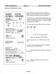
Flake Ice Machines General Information Model and Serial Number Format Model Numbers EF 80 0 A 1 Revision Level Condenser Type: A=Air W=Water R=Remote Voltage: 0=115V 5=240/50/1 6=208-230/60/1 Approximate 24 hour ice production: (x 10 @ 70°F/21°C Air and 50°F/10°C Water) Series: E=Environmental Flaker (Uses HFC Refrigerant) F=Self Contained Flake Ice Machine MF=Modular Flake Ice Machine Serial Number Date Code The first letter in the serial number indicates the month and decade of manufacture.
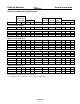
Flake Ice Machines General Information Electrical and Mechanical Specifications Production per 24 Hours @ Model Number No. of Minimum Max 90°FA 70°FW Compressor wires incl Circuit Fuse Lbs *RLA *LRA Voltage ground Ampacity Size Type Oz. Grams Kg ** Refrigerant EF Series / 60 Hertz Machines EF250A 319 145 5.7 30.2 115/60/1 3 12.4 15 R404A 12 340 EF450A 360 163 7.2 40 115/60/1 3 14.5 15 R404A 17 482 EF800A 616 280 10.4 51 115/60/1 3 18.
Flake Ice Machines General Information Installation Guidelines Note: Installation should be performed by an ICE-O-Matic trained Service Technician. For proper operation of the ICE-O-Matic ice machine, the following installation guidelines must be followed. Failure to do so may result in loss of production capacity, premature part failures, and may void all warranties.
Flake Ice Machines General Information EF Series Page A7
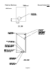
Flake Ice Machines General Information EMF Series Page A8
Flake Ice Machines General Information EMF Series (48 Inch Wide) Page A9
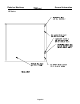
Flake Ice Machines General Information Remote Condenser Installation The EMF1106R2 and EMF2306R2 remote ice makers incorporate the mixing valve in the condenser. This configuration allows up to a 100 foot calculated remote line set run. Reference the diagram below to calculate the maximum 100 foot line set run. For proper operation of the ICE-O-Matic ice machine, the following installation guidelines must be followed.
Flake Ice Machines General Information ICE-O-Matic Parts and Labor Domestic & International Limited Warranty Mile High Equipment LLC (the “Company”) warrants ICE-O-Matic brand ice machines, ice dispensers, remote condensers, water filters, and ice storage bins to the end customer against defects in material and factory workmanship for the following: • Cube ice machines, compressed ice machines and remote condensers.
Flake Ice Machines General Information General Operation A general description of the flake ice machine operation is given below. The remainder of the manual provides more detail about the components and systems. Water enters a reservoir through the float valve and is gravity fed into the evaporator barrel through an opening in the bottom of the barrel. Water fills the evaporator to the same level as the water in the reservoir.
Flake Ice Machines Scheduled Maintenance Danger! Electrical shock and/or injury from moving parts inside this machine can cause serious injury or death. Disconnect electrical supply to machine prior to performing any adjustments or repair. Maintenance Procedure Warning! Failure to perform the required maintenance at the frequency specified will void warranty coverage in the event of a related failure.
Flake Ice Machines Scheduled Maintenance CAUTION: Protective eyewear and gloves should be worn when using cleaning products. CLEANING AND SANITIZING INSTRUCTIONS 1. Turn the machine and water supply to the float off. 2. Remove or melt all ice in the bin. 3. Prepare one gallon (3.75l) of non-chlorine ice machine cleaner i.e. Nu-Calgon Nickel Safe, as directed on container. 4. Turn the machine on, remove the float reservoir cover and add cleaning solution to the reservoir. 5.
Flake Ice Machines Winterizing Procedures Winterizing Procedures Important! Whenever the ice machine is taken out of operation during the winter months, the procedure below must be performed. Failure to do so may cause serious damage and will void all warranties. 1. Turn off water to machine. 2. Make sure all ice is out of the evaporator(s) 3. Place the ON/OFF switch to the “OFF” position. 4. Disconnect the tubing between the evaporator and water float. 5. Drain the water system completely. 6.
Flake Ice Machines Cabinet Care Cleaning Stainless Steel Commercial grades of stainless steel are susceptible to rusting. It is important that you properly care for the stainless steel surfaces of your ice machine and bin to avoid the possibility of rust or corrosion. Use the following recommended guidelines for keeping your stainless steel looking like new: 1. Clean the stainless steel thoroughly once a week. Clean frequently to avoid build-up of hard, stubborn stains.
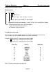
Flake Ice Machines Troubleshooting Trees How To Use The Troubleshooting Trees The troubleshooting trees were developed to be used in conjunction with the service information in the sections that follow. If used together as intended, these two parts of the manual will allow the ice machine service technician to quickly diagnose many of the problems encountered with the ice machines.
Flake Ice Machines Troubleshooting Trees Machine Runs, Does Not Make Ice Page C2
Flake Ice Machines Troubleshooting Trees Machine Runs, Does Not Make Ice Page C3
Flake Ice Machines Troubleshooting Trees Machine Does Not Run Page C4
Flake Ice Machines Troubleshooting Trees Slow Production Page C5
Flake Ice Machines Troubleshooting Trees Low Production Page C6
Flake Ice Machines Troubleshooting Trees High Suction Pressure Page C7
Flake Ice Machines Troubleshooting Trees Machine Freezes Up (Auger Seizes) Page C8
Flake Ice Machines Troubleshooting Trees Auger Motor Amp Draw Fluctuates Page C9
Flake Ice Machines Troubleshooting Trees Water Leaking From Bottom of Evaporator Page C10
Flake Ice Machines Troubleshooting Trees Machine Produces Wet Ice Page C11
Flake Ice Machines Troubleshooting Trees Hot Evaporator, Low Suction Pressure and Discharge Pressure (Remotes Only) Page C12
Flake Ice Machines Troubleshooting Trees Noise Coming from Evaporator Page C13
Flake Ice Machines Water System Water System The water system in the flaker uses a floated operated valve that maintains the water level in the evaporator barrel during ice making. Float Valve and Reservoir Water enters the machine through the float valve located in the water reservoir and is gravity fed into the evaporator barrel through the water inlet tube. As the evaporator fills with water, the inlet tube and reservoir will fill to the same level.
Flake Ice Machines Water System Water Seal and Lower O-Ring The water seal is located in the bottom of the evaporator and prevents water from leaking out of the evaporator. The water seal consists of two (2) components: the seal and the seal face. The seal is fitted into the lower bearing housing and the seal face fits around the auger shaft with the rubber side seating against the bottom of the auger. When the water seal assembly is in place, the top of the seal presses against the seal face.
Flake Ice Machines Drive System Drive System The drive system consists of all components used to turn the auger. The auger drive motor turns the gear reducer via a V-Belt. A coupler is used to connect the gear reducer to the auger. The auger is located in the evaporator and is supported by two bearings, one at each end. Evaporator Auger Drive Motor and V-Belt When facing the shaft, the auger motor should turn counter clockwise.
Flake Ice Machines Drive System Gear Reducer The gear reducer transfers torque to the auger. The auger drive motor turns the input shaft of the gear reducer at a high rate of speed. The input shaft turns a worm (screw type gear) that meshes with a worm gear (bronze gear). The worm gear turns the output shaft at a reduced speed. The gear reducer should be inspected for oil leakage, noise, and vibration during scheduled maintenance of the machine.
Flake Ice Machines Drive System Evaporator and Internal Components The evaporator assembly includes the evaporator and all of its internal components. The internal components consist of the upper and lower bearings and housings, water seal assembly, upper and lower O-Rings, auger, and upper and lower nuts. The evaporator assembly will need to be disassembled for inspection or repair if one or more of the following conditions exist. • Metal particles in the ice. • Grease in the ice.
Flake Ice Machines Drive System Remove the upper evaporator retaining nut by using a chain wrench (wrap chain around the upper part of the nut) to loosen the nut. Setscrews are not used on the upper nut. (Right Hand Thread) Caution: Do not use a hammer and chisel to loosen the nut, as damage will result.
Flake Ice Machines Drive System Vertical Score Lines Guide the Ice Upward Evaporator Barrel and Auger Inspection Inspect the evaporator for damage around the dispense opening. If it is cracked or bulged outward, it is probably due to a bin control failure. Check both bin controls for proper adjustment and operation before the machine is put back into service. Inspect the interior of the evaporator barrel for damage.
Flake Ice Machines Drive System Bearings, Water Seal and O-Rings There is a bearing at the top and bottom of the auger shaft to allow the auger to rotate freely with a minimum amount of friction. The lower bearing is a sealed ball bearing and the upper bearing is a tapered roller bearing. Tap the upper race out of the bearing housing. The bearings can be inspected once removed from the machine by turning the bearing by hand. If the bearing does not turn smoothly, it should be replaced.
Flake Ice Machines Drive System Torque bolt to 40 ft/lbs. Seal Face Installation Lightly lubricate the rubber portion of the seal face and Pack bearing with grease prior to apply a small amount of silicone sealant to the metal installation part of the seal face (rubber side) that seats against Fill cavity with grease the auger. Install the seal face on the auger. Caution: Do not scratch or damage the seal face.
Flake Ice Machines Drive System Exploded View of the Evaporator Page E8
Flake Ice Machines Refrigeration System Refrigeration System and Components Before diagnosing the refrigeration system, it is important that the refrigerant charge be correct. Whenever the refrigeration system has been opened, the filter-drier must be replaced and the proper refrigerant charge must be weighed in or measured. See refrigerant charge information on Page A5. Refrigerant is circulated throughout the refrigeration system by a hermetic compressor.
Flake Ice Machines Refrigeration System Refrigerant Pressures (Continued) The operating pressures for models utilizing the Alco thermostatic expansion valve are listed below.
Flake Ice Machines Refrigeration System Refrigerant Pressures (Continued) The operating pressures for models utilizing the Sporlan thermostatic expansion valve are listed below.
Flake Ice Machines Refrigeration System To properly cool the condenser, there must be adequate airflow around the machine. The ambient air temperature should not exceed 100°F (38°C). See Installation Guideline on Page A6. The condenser coil and fan blades must be kept clean. The condenser can be cleaned with compressed air or by using a brush. If a brush is used, brush in the direction of the fins taking care not to bend or distort the condenser fins.
Flake Ice Machines Refrigeration System Expansion Valve The expansion valve meters the flow of refrigerant into the evaporator, changing its state from a high pressure liquid to a low pressure liquid. This drop in pressure causes the refrigerant to cool. The cooled refrigerant absorbs heat from the water in the evaporator. The flow of refrigerant into the evaporator is controlled by the temperature at the outlet of the evaporator.
Flake Ice Machines Refrigeration System Expansion Valve Diagnosis Symptom Single Evaporator Machine 1. Evaporator flooded but suction pressure too high. Compressor has been checked and appears to be good. Suction line at compressor may be colder than normal. 2. Evaporator starved, no frost on line exiting evaporator. Suction pressure low. a. b. c. d. Problem TXV sensing bulb uninsulated or not making good contact with suction line. TXV sensing bulb in wrong location. System overcharged. TXV stuck open.
Flake Ice Machines Refrigeration System Evaporator When water fills the evaporator, liquid refrigerant is circulated through the tubing wrapped around the evaporator. As the liquid refrigerant in the tubing vaporizes, it absorbs heat from the water, causing it to freeze. The evaporator should be completely flooded with refrigerant while the machine is making ice. A flooded evaporator will build ice evenly in the evaporator. A starved evaporator will produce less ice and the ice will be wetter than normal.
Flake Ice Machines Refrigeration System Remote System Machines that use remote condensers have several components that are not used in self contained machines. A mixing valve controls the head pressure when the ambient temperature at the condenser drops below 70°F (21°C). When the bin fills with ice or is turned off at the selector switch, the machine will pump all the refrigerant into the receiver before shutting off. Remote Condenser For proper operation, the remote condenser must be installed properly.
Flake Ice Machines Refrigeration System Mixing Valve Diagnosis: Problem Possible Cause Remedy 1. Head pressure low, Line between valve and receiver cold. Ambient condenser temp. below 70°F (21°C) a. Valve defective, not allowing discharge gas into receiver a. Replace valve 2. Head pressure low, Line between valve and receiver hot. a. System low on charge. b. Valve defective, not allowing liquid into receiver. a. Leak check. Recover refrigerant and weigh in proper charge. b. Replace valve. a.
Flake Ice Machines Refrigeration System Receiver If the system has a remote condenser, the refrigerant will enter a receiver before passing through the filter drier. The receiver holds reserve liquid refrigerant during the freeze cycle. The receiver also stores liquid refrigerant during the off cycle. Refrigerant Refrigerant in a high-pressure liquid form is fed to an expansion valve where the refrigerant is reduced to a low-pressure liquid.
Flake Ice Machines Refrigeration System Method of Charging Refrigerant In order to achieve a properly charged refrigeration system, the system must be completely evacuated. To achieve a complete evacuation you will need a service gauge manifold with properly maintained hoses, and a vacuum pump capable of pulling a 50-micron vacuum. This will require a two-stage pump. Connect the service gauge manifold to the high and low side service ports and vacuum pump.
Flake Ice Machines Refrigeration System Remote models with sixty (60) foot lineset runs will need an additional fifteen (15) ounces of refrigerant added. In some cases the complete refrigerant charge may not enter the refrigeration system. In those instances, close the gauge manifold high side valve and disconnect the manifold from the high side port. When the icemaker is completely charged, secure the caps to the service ports and check to make sure the ports are not leaking refrigerant.
Flake Ice Machines Electrical System Control Circuit All machines in this manual are controlled basically the same way. Selector Switch The selector switch is used to start the ice making cycle or to turn the machine off. The machine is put into operation by switching the selector switch to the ON position. Contactor When the selector switch is in the ICE position, the contactor coil is energized and pulls in the contactor contacts.
Flake Ice Machines Electrical System Compressor Check Disconnect power before servicing If the compressor uses an internal overload, be certain that the compressor has cooled and the overload has reset before diagnosing the compressor. If the compressor is cool and is still not running, check the compressor motor windings by first removing the wires at the compressor terminals.
Flake Ice Machines Electrical System Safety Control The low temperature safety control prevents the machine from operating without water in the evaporator of if the v-belt breaks. If the evaporator temperature drops below approximately 30°F (-1°C), the safety control will open and shut the machine off. Adjustment Screw The safety control is located in the control box and the capillary tube is located in a thermal well attached to the bottom of the evaporator barrel just above the lower nut.
Flake Ice Machines Electrical System Mechanical Bin Control The mechanical bin control is located in the top panel of the ice bin on the EF Series and on the top of the down chute on the EMF Series. When ice fills the down chute on the EMF Series units, or ice fills the bin on EF Series units a rubber diaphragm pushes up against a switch. To check the bin switch, push up on the diaphragm or switch arm raising it approximately 1/8 inch. This movement should actuate (open) the switch.
Flake Ice Machines Electrical System Compressor Delay When the machine starts, the compressor delay timer is energized. Once the timer counts out, the contactor is energized and the compressor starts. The compressor delay timer will keep the compressor off for approximately 5 minutes when the machine restarts for any reason. This will reduce the load on the auger drive system. On remote units, the compressor delay timer energizes the liquid line solenoid.
Flake Ice Machines Electrical System EF250/255/405 EF450A/W 9071694-01 Page G6
Flake Ice Machines Electrical System EF800A/W 9071963-01 Page G7
Flake Ice Machines Electrical System EMF450/405A/W 9071958-01 Page G8
Flake Ice Machines Electrical System EMF800A/W 9071954-01 Page G9
Flake Ice Machines Electrical System EMF705/1005/1006A/W 9071956-01 Page G10
Flake Ice Machines Electrical System EMF1106R 9071962-01 Page G11
Flake Ice Machines Electrical System EMF2306A/W 9071955-01 Page G12
Flake Ice Machines Electrical System EMF2306R 9071960-01 Page G13
Flake Ice Machines Electrical System EMF2305L 9071959-01 Page G14