ELEVATION SERIES CUBE ICE MAKER CIM Modular Cubers Technical Service Manual Ice-O-Matic 11100 East 45th Avenue Denver, Colorado 80239 1-800-423-3367 10/2017
ELEVATION SERIES CIM CUBERS TABLE OF CONTENTS INTRODUCTION …………………………………………………………………………………………………………………………………… 1 AIR AND WATER COOLED INSTALLATION GUIDELINES ………………………………………………………………………… 2 REMOTE INSTALLATION GUIDELINES ………………………………………………………………………………………………….. 3 ELECTRICAL AND PLUMBING REQUIREMENTS ……………………………………………………………………………………. 7 START-UP PROCEDURES ……………………………………………………………………………………………………………………… 8 SEQUENCE OF OPERATIONS ………………………………………………………………………………………………………………..
ELEVATION SERIES CIM CUBERS INTRODUCTION Energy Efficiency Ice-O-Matic has partnered with ENERGY STAR since 2004 to ensure our customers receive the most efficient ice machines for your investment dollar. Ice-O-Matic is committed to the continuous improvement in both energy efficiency and productivity thereby delivering the best value in energy efficient ice machines money can buy. For a detailed list of ENERGY STAR qualified Ice-O-Matic ice machines, go to: http://www.iceomatic.
ELEVATION SERIES CIM CUBERS INSTALLATION GUIDELINES Installation Guidelines Water Filtration/Treatment For proper operation of the ice machine, the following installation guidelines must be followed by a qualified refrigeration technician. Failure to do so may result in loss of production capacity, premature part failures, and may void all warranties. Reference the installation parameters prior to installing the machine. Ice-O-Matic assumes no responsibility for improperly installed equipment.
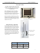
ELEVATION SERIES CIM CUBERS INSTALLATION GUIDELINES Clearance Requirements Electrical Specifications Self-contained air-cooled ice machines should have a minimum of 6 inches (15cm) of clearance at the rear, top and sides for proper air circulation and adequate space for serviceability. Self-contained air-cooled ice machines exhaust air out the top and right side. There are two alternative air exhaust options.
ELEVATION SERIES CIM CUBERS REMOTE CONDENSER GUIDELINES Remote Condenser Installation For proper operation of the ice machine, the following installation guidelines must be followed. Failure to do so may result in loss of production capacity, premature part failure, and may void all warranties.
ELEVATION SERIES CIM CUBERS Route the refrigerant lines through the roof opening. Follow straight line routing whenever possible. Any excess tubing MUST remain inside the building. Spiral the excess length of precharged tubing inside the building. Use a horizontal spiral to avoid any traps in the lines. Have the roofing contractor seal the holes in the roof per local codes. REMOTE CONDENSER GUIDELINES CAUTION: The couplings on the sets of pre-charged lines are self sealing when installed properly.
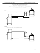
ELEVATION SERIES CIM CUBERS REMOTE CONDENSER GUIDELINES Equivalent Run Calculation Examples Formula for maximum equivalent run: (RISE x 1.7) + (DROP x 6.6) + HORIZONTAL RUN = EQUIVALENT RUN NOT TO EXCEED 100 CALCULATED FEET Rise: (35 ft. x 1.7) + (40 ft.) = 99.5 equivalent feet line run 35 ft. rise 40 ft. horizontal Drop: (10 ft. x 6.6) + (34 ft.) = 100 equivalent feet line run 10 ft. drop 34 ft.
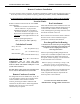
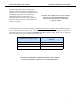
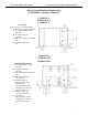
ELEVATION SERIES CIM CUBERS ELECTRICAL AND PLUMBING REQUIREMENTS Electrical and Plumbing Requirements CIM SERIES Common Connections CIM0330/5 A CIM0430/5/6 A CIM0635/6 A Air Cooled Please note: air-cooled units require 6”(152mm) for air intake and exhaust. A. Ice maker potable water in, 3/8” FPT. B. Ice maker water out, 3/4” FPT. C. Hole for electrical connections, 7/8”. D. Electrical junction box, 7/8”. CIM0330 W CIM0430/5/6 W CIM0636 W/R Water/Remote Cooled A. Ice maker potable water in, 3/8” FPT. B.
ELEVATION SERIES CIM CUBERS START-UP PROCEDURE Start-Up Procedure Note: Before starting the machine, make sure the machine is level within 1/8 inch in all directions, the bin or dispenser leg height can be adjusted by rotating the leg foot. After verifying proper voltage, water supply, drains and breathable air space around the unit, press and quickly release the ON/OFF button behind the unit front panel. The indicator light will change from a solid red to solid blue in color.
ELEVATION SERIES CIM CUBERS SEQUENCE OF OPERATIONS SEQUENCE OF OPERATIONS BLUE w/ WHITE BLUE w/ RED WHITE WHITE R1 = Illuminated LED 12V DC Switches BLUE R2 R3 R4 R5 R6 BLUE BLACK TAN YELLOW BROWN VIOLET RED PINK Line Voltage Components CONTROL BOARD - OFF STATUS When power is initially applied to the unit, the LED’s on both the Push Pad and the Board POWER Button will flash in sequence BLUE, then RED, then the WASH Button will flash YELLOW, followed by the POWER Button LED will turn a solid R
ELEVATION SERIES CIM CUBERS SEQUENCE OF OPERATIONS BLUE w/ WHITE BLUE w/ RED WHITE WHITE R1 = Illuminated LED 12V DC Switches BLUE R2 R3 R4 R5 R6 BLACK BLUE TAN YELLOW BROWN VIOLET RED PINK Line Voltage Components CONTROL BOARD - FREEZE CYCLE A quick press of the POWER button on the Push Pad or Board will start the Freeze cycle. The Water Inlet Valve will be energized (R4 LED on Board illuminated) and water will begin flowing into the Sump.
ELEVATION SERIES CIM CUBERS SEQUENCE OF OPERATIONS BLUE w/ WHITE BLUE w/ RED WHITE WHITE R1 = Illuminated LED 12V DC Switches BLUE R2 R3 R4 R5 R6 BLACK BLUE TAN YELLOW BROWN VIOLET RED PINK Line Voltage Components CONTROL BOARD - COMPRESSOR START The Hot Gas Valve will be energized (R3 on Board illuminated) for 5 seconds and the system pressures will start to equalize.
ELEVATION SERIES CIM CUBERS SEQUENCE OF OPERATIONS BLUE w/ WHITE BLUE w/ RED WHITE WHITE R1 = Illuminated LED 12V DC Switches BLUE R2 R3 R4 R5 R6 BLACK BLUE TAN YELLOW BROWN VIOLET RED PINK Line Voltage Components CONTROL BOARD - COMPRESSOR START The Compressor will be energized (R2 on Board illuminated) and the Hot Gas Valve will remain open for 5 more seconds and then de-energize (R3 on Board off).
ELEVATION SERIES CIM CUBERS SEQUENCE OF OPERATIONS BLUE w/ WHITE BLUE w/ RED WHITE WHITE R1 = Illuminated LED 12V DC Switches BLUE R2 R3 R4 R5 R6 BLUE TAN YELLOW BLACK BROWN VIOLET RED PINK Line Voltage Components CONTROL BOARD - PRE-CHILL The Compressor and Fan(s)/Liquid Line Solenoid (R1 and R2 LED’s on Board illuminated) are energized and unit is now in a Pre-Chill for 30 seconds bringing the Evaporator temperature down. Both Curtain Switch LED’s are on showing closed curtain(s).
ELEVATION SERIES CIM CUBERS SEQUENCE OF OPERATIONS BLUE w/ WHITE BLUE w/ RED WHITE WHITE R1 = Illuminated LED 12V DC Switches BLUE R2 R3 R4 R5 R6 BLACK BLUE TAN YELLOW BROWN VIOLET RED PINK Line Voltage Components CONTROL BOARD - FREEZE The Water Pump is energized (R6 LED on Board illuminated) and water is pushed through the Water Pump Tube and flows over the Evaporator. The High Float Switch contacts close as the water level in the Sump drops (High Float Switch LED on Board illuminates).
ELEVATION SERIES CIM CUBERS SEQUENCE OF OPERATIONS BLUE w/ WHITE BLUE w/ RED WHITE WHITE R1 = Illuminated LED 12V DC Switches BLUE R2 R3 R4 R5 R6 BLACK BLUE TAN YELLOW BROWN VIOLET RED PINK Line Voltage Components CONTROL BOARD - ANTI-SLUSH During the first 3 cycles as the water temperature reaches 36 degrees F. the Water Pump will shut off for 20 seconds to reduce the possibility of slush developing in the Sump.
ELEVATION SERIES CIM CUBERS SEQUENCE OF OPERATIONS BLUE w/ WHITE BLUE w/ RED WHITE WHITE R1 = Illuminated LED 12V DC Switches BLUE R2 R3 R4 R5 R6 BLUE TAN YELLOW BLACK BROWN VIOLET RED PINK Line Voltage Components CONTROL BOARD - WATER PUMP ON At the end of Anti-Slush the Water Pump (R6) will be re-energized and water starts flowing over the Evaporator again. The unit will stay in this mode until the Low Float Switch closes on water level drop, indicating the unit is ready to harvest.
ELEVATION SERIES CIM CUBERS SEQUENCE OF OPERATIONS BLUE w/ WHITE BLUE w/ RED WHITE WHITE R1 = Illuminated LED 12V DC Switches BLUE R2 R3 R4 R5 R6 BLUE TAN YELLOW BLACK BROWN VIOLET RED PINK Line Voltage Components CONTROL BOARD - INITIATING HARVEST When the water level in the SUMP drops to close the contacts of the Low Float Switch (LED on Board illuminates) after a 5 second de-bounce of the switch will signal the start of the Harvest Cycle.
ELEVATION SERIES CIM CUBERS SEQUENCE OF OPERATIONS BLUE w/ WHITE BLUE w/ RED WHITE WHITE R1 = Illuminated LED 12V DC Switches BLUE R2 R3 R4 R5 R6 BLUE TAN YELLOW BLACK BROWN VIOLET RED PINK Line Voltage Components CONTROL BOARD - HARVEST After the contacts of the Low Float Switch close, the Harvest Cycle starts by energizing the Hot Gas Valve, Harvest Assist, Purge Valve AND Water Inlet Valve (R2, R3, R4, R5 and R6 are illuminated on Air and Water Cooled units, ALL Relays are energized on Remo
ELEVATION SERIES CIM CUBERS SEQUENCE OF OPERATIONS BLUE w/ WHITE BLUE w/ RED WHITE WHITE R1 = Illuminated LED 12V DC Switches BLUE R2 R3 R4 R5 R6 BLACK BLUE TAN YELLOW BROWN VIOLET RED PINK Line Voltage Components CONTROL BOARD - HARVEST After the Purge Valve and Water Pump de-energize, the Water Inlet Valve will remain open for 20 seconds, partially filling the SUMP in preparation for the next Freeze Cycle (R2, R3, and R4, are illuminated on Air and Water Cooled units, R1 is also energized on
ELEVATION SERIES CIM CUBERS SEQUENCE OF OPERATIONS BLUE w/ WHITE BLUE w/ RED WHITE WHITE R1 = Illuminated LED 12V DC Switches BLUE R2 R3 R4 R5 R6 BLUE TAN YELLOW BLACK BROWN VIOLET RED PINK Line Voltage Components CONTROL BOARD - HARVEST After the Water Inlet Valve closes following the 20 second time out, the Hot Gas Valve and Harvest Assist will remain energized until the ice slab is harvested from the Evaporator.
ELEVATION SERIES CIM CUBERS SEQUENCE OF OPERATIONS BLUE w/ WHITE BLUE w/ RED WHITE WHITE R1 = Illuminated LED 12V DC Switches BLUE R2 R3 R4 R5 R6 BLACK BLUE TAN YELLOW BROWN VIOLET RED PINK Line Voltage Components CONTROL BOARD - BIN FULL As the ice slab falls from the Evaporator, the Curtain(s) is pushed out, contacts of the Magnetic Curtain Switch(s) open as the ice slab falls. If the Curtain(s) remains open for 30 seconds, the unit will shut down on a full bin.
ELEVATION SERIES CIM CUBERS SEQUENCE OF OPERATIONS BLUE w/ WHITE BLUE w/ RED WHITE WHITE R1 = Illuminated LED 12V DC Switches BLUE R2 R3 R4 R5 R6 BLACK BLUE TAN YELLOW BROWN VIOLET RED PINK Line Voltage Components CONTROL BOARD - RETURN TO FREEZE As the ice slab falls from the Evaporator, the Curtain(s) is pushed out and the contacts of the Curtain Switch(s) open and close, terminating the Harvest Cycle.
ELEVATION SERIES CIM CUBER CONTROL BOARD Control Board Operation The Board controls the operation of the unit. A series of LED lights show Switch positions and Component operation to assist the technician in understanding and troubleshooting issues that may arise. See Sequence of Operation pg. 9 for operational information.
ELEVATION SERIES CIM CUBER CONTROL BOARD Adjustment Switch Block Three adjustments can be made on the block. Extended Purge, Bin Thermostat Kit add-on and Cleaning Needed Reminder. Standard Purge time during a Defrost Cycle is set at 7 seconds. To add an additional 5 seconds to the purge time, move Switch 1 to the right, to the ON position. Should the unit be installed on top of a dispenser, a Bin Thermostat Kit is required.
ELEVATION SERIES CIM CUBER CONTROL BOARD Power and Clean LED Flash Description SOLID - On Constantly SLOW - Flashes once every second QUICK - Flashes once every half second DOUBLE SLOW - Flashes twice then 1 second delay DELAYED - flashes once every 3 seconds Error Codes Error 1 - POWER LED QUICK FLASH RED - Unit has experienced a MAX Freeze (1 hr), MAX Harvest (5.5 minutes) or BOTH. Error 2 - POWER LED SLOW FLASH IN OFF STATE ONLY - Thermistor Failure.
ELEVATION SERIES CIM CUBERS BOARD COMPONENT LED SEQUENCE BOARD LED SEQUENCE DURING OPERATION - INITIAL FREEZE CYCLE AT START-UP 26
ELEVATION SERIES CIM CUBERS BOARD COMPONENT LED SEQUENCE BOARD LED SEQUENCE DURING OPERATION - INITIAL HARVEST CYCLE AT START-UP 27
ELEVATION SERIES CIM CUBERS BOARD COMPONENT LED SEQUENCE BOARD LED SEQUENCE DURING OPERATION - TRANSITION FROM HARVEST TO FREEZE 28
ELEVATION SERIES CIM CUBERS BOARD COMPONENT LED SEQUENCE BOARD LED SEQUENCE DURING OPERATION - BIN FULL (CURTAIN OR STAT) 29
ELEVATION SERIES CIM CUBERS BOARD COMPONENT LED SEQUENCE BOARD LED SEQUENCE DURING OPERATION - DIAGNOSTICS IN FREEZE CYCLE The Diagnostic sequence is started by pressing both the Power and Clean buttons for 6 seconds.
ELEVATION SERIES CIM CUBERS BOARD COMPONENT LED SEQUENCE BOARD LED SEQUENCE DURING OPERATION - DIAGNOSTICS IN HARVEST CYCLE 31
ELEVATION SERIES CIM CUBERS BUTTON FUNCTIONS 32
ELEVATION SERIES CIM CUBER SUMP Sump The Sump holds the potable water for the Freeze Cycle.It is located under the Evaporator and accessible from the front of the unit. The Sump must be removed to access the Water Pump and the Float Switch Housing. Splash Guard Splash Curtain SUMP Sump Removal First remove the Splash Curtain and Splash Guard. Disconnect Water Pump Tube as shown above and tuck backside of tube into the Sump.
ELEVATION SERIES CIM CUBER SUMP Sump Retainer Lift front of Sump and pull forward to clear the Sump Retainers from the frame. Support Tab With the Support Tabs now clear of the frame, allow the back of the Sump to fall clear of the frame. Again lift the front of the Sump and push towards the back and down until Sump is clear of the frame. Turn the Sump sideways and remove through the ice drop zone. To re-install, reverse process making sure to tuck Water Pump Tube into Sump as lift Sump into place.
ELEVATION SERIES CIM CUBER HIGH AND LOW FLOAT SWITCHES AND HOUSING Float Housing Assembly The Float Switch Housing Assembly contains the High and Low Float Switches along with the Sump Thermistor. See below for function of each. See also Sequence of Operation pg. 9. High Float Switch Closed Position Low Float Thermistor Switch Opens half way up Stem. Switch Closed Position High Float Switch Function Switch Opens half way up Stem.
ELEVATION SERIES CIM CUBER HIGH AND LOW FLOAT SWITCHES AND HOUSING the Sump during the Freeze Cycle. During the first 3 cycles following a full bin shut down or being turned on (initial start-up), the unit will perform an “Anti-slush” shutdown of the Water Pump for 20 seconds when the water temperature reaches 36 degrees F to reduce the possibility of the water in the Sump slushing. The unit will perform an anti-slush shut down of the Water Pump any time the water temp reaches 28 degrees F.
ELEVATION SERIES CIM CUBER HIGH AND LOW FLOAT SWITCHES AND HOUSING The Bridge Thickness on units under 400# production should be 3/16” while units over 400# production should be 1/8” thick when measured across the middle of the plate. Minor Adjustments can be made to the bridge thickness by moving the Water Level Adjustment Arm of the Float Housing up for a thinner bridge or down for a thicker bridge.
ELEVATION SERIES CIM CUBER WATER PUMP Water Pump Operation Relay 6 on the Board (LED ON) energizes the Water Pump after the 30 second Pre-Chill of the Evaporator during the Freeze Cycle. In the first 3 Freeze Cycles after a shutdown (turned OFF or Bin Full) the Water Pump will perform a shutdown for 20 seconds to help prevent the Sump from slushing. The Water Pump will then be energized to complete the Freeze Cycle (see Sequence of Operations pg.
ELEVATION SERIES CIM CUBER WATER PUMP Water Pump Removal The “foot” of the Water Pump points towards the right front corner of the unit. Grasp the foot and turn counter clockwise. When the foot points towards the right rear corner, you will feel the weight of the pump as the collar clears the base connections. Lower the Water Pump and disconnect. Re-install the Water Pump by first making the electrical connection, the push Pump up pointing the Foot at the right rear corner and turn clockwise to secure.
ELEVATION SERIES CIM CUBER WATER DISTRIBUTION TUBE Water Distribution Tube The Water Distribution Tube has an inner tube and an outer tube. The water enters through the inner tube and sprays the water up into the outer tube relieving the pressure on the water. Gravity takes over and the water runs out the outer tube holes pointed down. The water runs smoothly and evenly over the Evaporator. Removal and Disassembly Disconnect Water Pump Tube from Water Distribution Tube.
ELEVATION SERIES CIM CUBER WATER DISTRIBUTION TUBE The Water Distribution Tube comes apart easily. It should be taken apart and cleaned regularly along with the rest of the unit. The pieces are Pokeyoke, meaning it only goes back together one way.
ELEVATION SERIES CIM CUBER WATER INLET VALVE Water Inlet Valve Operation Relay 4 on the Board (LED ON) energizes the Valve first on initial start-up to fill the Sump until the contacts of the High Float Switch open, indicating a proper amount of water for ice making. The purpose is to verify water supply before starting the unit.
ELEVATION SERIES CIM CUBER PURGE VALVE Purge Valve Operation The Purge Valve is located in the back of the Evaporator. The Valve should open when energized by Relay 5 on the Board (LED ON) during the Harvest Cycle to help empty the mineral laden water (see Sequence of Operation pg. 9) and during the Cleaning/Sanitizing Cycle (see Cleaning Instructions pg. 56). Troubleshooting The Purge Valve is located in the back of the Evaporator.
ELEVATION SERIES CIM CUBER HARVEST ASSIST ASSEMBLY/HOT GAS VALVE Harvest Assist Assembly/Hot Gas Valve Operation The Harvest Assist Assembly is mounted to the back of the Evaporator Assembly. It is energized by Relay 3 along with the Hot Gas Valve. As the unit enters the Harvest Cycle, Relay 3 will illuminate indicating voltage is being sent to the Harvest Assist Assembly and the probe will be pushed forward to meet the ice slab.
ELEVATION SERIES CIM CUBER EVAPORATOR Evaporator Assembly The nickel plated Evaporator Assembly has a copper core to assure good heat transfer. Water is pumped gently over the Evaporator during the freeze cycle for even ice formation. Evaporator Operation The Evaporator should be fully flooded with refrigerant for most of the freeze cycle to assure even ice formation. The serpentine on the back of the Evaporator starts at the bottom right corner of the plate (viewed from the front).
ELEVATION SERIES CIM CUBERS EVAPORATOR REPLACEMENT While recovering the refrigerant from the unit, disconnect High and Low Float Switches, Thermistor, Curtain Switch and Push Pad ribbon and move the wiring clear of the area. Connectors Evaporator Top Remove the Splash Curtain, Evaporator Cover, Top Evaporator Cover, Water Distribution Tube, Water Pump Tube and its connector, Sump, Water Pump, and Float Switch Housing Assembly.
ELEVATION SERIES CIM CUBERS EVAPORATOR REPLACEMENT 47
ELEVATION SERIES CIM CUBERS EVAPORATOR REPLACEMENT Surround Pull bottom of frame out to clear left hand surround. Grasp and remove Evaporator freeing the Left Hand side first. The Left Hand Surround will come out with the Evaporator; the Right Hand surround will be left in place. Once the Evaporator is out, separate the surround from the Evaporator by removing the five – 1/4” Screws on the Left Hand side of the Evaporator.
ELEVATION SERIES CIM CUBER MAGNETIC CURTAIN SWITCH Magnetic Curtain Switch The Magnetic Curtain Switch is a proximity switch that closes the contacts when the Splash Curtain closes. LED’s on the Board indicate a closed switch when illuminated. Magnet Connector Troubleshooting Should the LED’s on the Board be off when the Splash Curtain is closed, first verify the magnet is in place on the Splash Curtain and the Wiring Harness is properly connected at the Switch and at the Board.
ELEVATION SERIES CIM CUBER HIGH PRESS CUT-OUT AND FAN CYCLE SWITCH High Pressure Cut-out (left) The High Pressure Cut-out is set to open at 450 psig and de-energizes the Contactor as a safety on the unit. Fan Cycle Control (right) The Fan Cycle Control helps maintain head pressure in cooler ambient temps. The control closes at 250 psig, energizing the Fan Motor and opens at 200 psig.
ELEVATION SERIES CIM CUBER HIGH TEMP SAFETY High Temp Safety The High Temp Safety is a bi-metal thermostat strapped to the line at the outlet of the Hot Gas Valve. Should the Hot Gas Valve stick open and the refrigerant line reach 180 degrees F., the High Temp Safety would open, dropping power to the Contactor and shut down the Compressor. When the line temperature drops below 120 degrees F., the contacts of the Safety will close, allowing power to the Contactor.
ELEVATION SERIES CIM CUBER FAN MOTOR Fan Motor Operation The Fan Motor (Self Contained Air Cooled Units) is Mounted to the Fan Shroud covering the Condenser at the rear of the unit. It is energized by Relay 1 and controlled by the Fan Cycling Switch. The Switch should close at 250 psi of head pressure and power the Motor. The Fan Cycle Switch should open at 200 psi of head and the Fan Motor will deenergize.
ELEVATION SERIES CIM CUBER REFRIGERATION SECTION REFRIGERATION SECTION The Refrigeration Section on a CIM Cuber contains the Compressor, Thermostatic Expansion Valve, Hot Gas Valve and Condenser. Remote systems also utilize a Mixing Valve (LAC), Liquid Line Solenoid and Receiver. Refrigeration Section Operation The Compressor drives the refrigeration system. Ice-O-Matic uses a Thermostatic Expansion Valve to control refrigerant flow through the Evaporator.
ELEVATION SERIES CIM CUBER REFRIGERATION SECTION Hot Gas Valve The Hot Gas Solenoid Valve opens to provide gas to the Evaporator during the Harvest Cycle. Troubleshooting - Hot Gas Valve Should the valve not open at the initiation of the Harvest Cycle (R3 LED ON), verify voltage at the coil of the solenoid. If no voltage is present, verify Molex is properly connected at Board and Voltage is present at Molex. If Voltage is present at coil, verify resistance through coil.
ELEVATION SERIES CIM CUBERS GENERAL MAINTENANCE Electrical shock and/or injury from moving parts inside this machine can cause serious injury. Disconnect electrical supply to machine prior to performing any adjustments or repairs. Failure to perform the required maintenance at the frequency specified will void warranty coverage in the event of a related failure.
ELEVATION SERIES CIM CUBERS CLEANING/SANITIZING PROCEDURES Cleaning Instruction for Ice-O-Matic CIM Series Ice Machines Note: Proper cleaning of an ice machine requires two parts: descaling and sanitizing. Descaling should be scheduled at a minimum of twice per year but no more than once per month. Descaling dissolves the mineral deposits on the evaporator and other surfaces. It removes scale, calcium, lime scale and other mineral buildup.
ELEVATION SERIES CIM CUBERS 6. 7. 8. 9. CLEANING/SANITIZING PROCEDURES Quick press the CLEAN button to start the process. Ice machine will show a solid red and flashing yellow light during the cleaning cycle. The machine will first verify that the sump is empty with the pump ON and the purge valve energized. When the sump is mostly empty, the machine will begin to fill the sump (about 30 seconds to a minute). The pump turns ON when the water fill reaches the proper fill level.
ELEVATION SERIES CIM CUBERS CABINET CARE Chemicals for Descaling and Sanitizing It is important to use solutions that do not harm the ice machine.
ELEVATION SERIES CIM CUBERS WINTERIZING PROCEDURES Winterizing Procedures IMPORTANT: Whenever the ice machine is taken out of operation during the winter months, the procedure below must be performed. Failure to do so may cause serious damage and will void all warranties. 1. Turn off water to machine. 2. Make sure all ice is off of the evaporator(s). If ice is being made, initiate harvest by pressing the Power Button for approximately 3 seconds. The unit will shut off automatically following the harvest.
ELEVATION SERIES CIM CUBERS TECHNICAL SPECIFICATIONS 60
ELEVATION SERIES WIRING DIAGRAM CIM0330, 0430, 0436, 0530, 0636 Air and Water Cooled Units 61
ELEVATION SERIES CIM CUBERS WIRING DIAGRAM CIM0335, 0435, 0535, 0635 Air and Water Cooled Units 62
ELEVATION SERIES CIM CUBERS WIRING DIAGRAM CIM0530, 0636 Remote Cooled Units 63
ELEVATION SERIES WIRING DIAGRAM CIM0535 Remote Cooled Units 64