
Instruction Manual


1. General Introduction
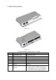
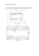
Figure 1- 1
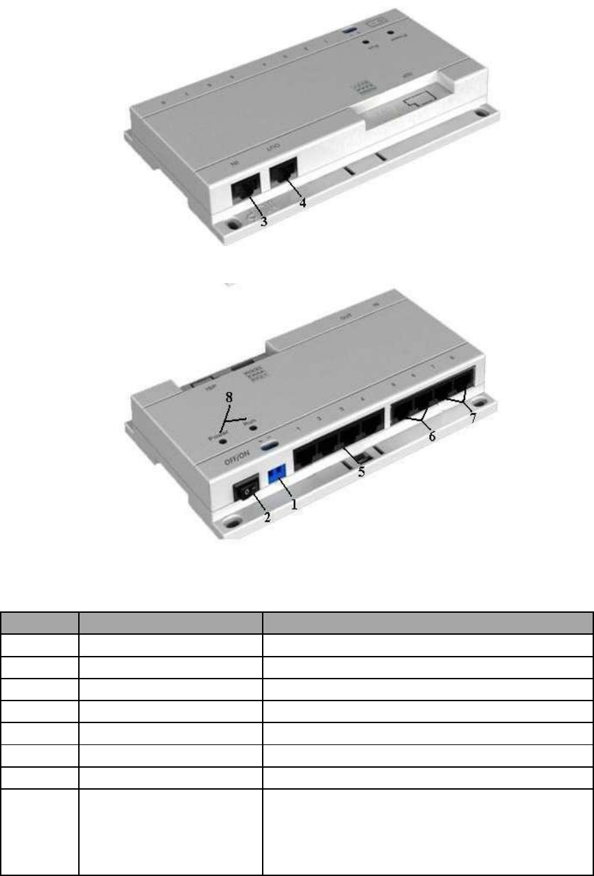
Figure 1- 2
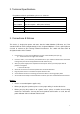
For product detailed information, please see below
No.
Name
Description
1
AC IN Power Plug
24V AC Power Input
2
OFF/ON Power Switch
Power Switch
3
Up Interface IN
Switch cascading up port
4
Down Interface OUT
Switch cascading down port
5
Port 1~4
Connect VTH Monitor 1~4
6
Port 5~6
Connect VTH Monitor 5~6
7
Port7~8
Reserved
Power indicator: Red. Indicator On: Power
8
Indicator
supply is normal. Indicator Off: No power.
Run indicator: Yellow-Green. Indicator keeps
on or flashes: Device working as normal.
1