Intercom Switch IH-S1030 User’s Manual
Table of Contents Caution ...................................................................................................................................... ii 1. General Introduction ................................................................................................................ 1 2. Technical Specifications ............................................................................................................ 2 3. Connections & Notices .............................................
Caution All installation and operation here should conform to your local electrical safety codes. We assume no liability or responsibility for any fires or electrical shock caused by improper handling or installation. We arenot liable for any problems caused by unauthorized modifications or attempted repair. The device should be installedin a cool, dry place away from direct sunlight, inflammable, explosive substances and etc.
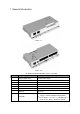
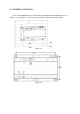
1. General Introduction Figure 1- 1 Figure 1- 2 For product detailed information, please see below No. Name Description 1 AC IN Power Plug 24V AC Power Input 2 OFF/ON Power Switch Power Switch 3 Up Interface IN Switch cascading up port 4 Down Interface OUT Switch cascading down port 5 Port 1~4 Connect VTH Monitor 1~4 6 Port 5~6 Connect VTH Monitor 5~6 7 Port7~8 Reserved 8 Indicator Power indicator: Red. Indicator On: Power supply is normal. Indicator Off: No power.
2. Technical Specifications For product technical specifications, please see Chart 2- 1. Model IH-S1030 Voltage 24V AC Power Consumption Standby consumption:0.2 W (under free load); Max consumption:45W (under full load) Work Temp -10℃~55℃ Dimensions 179 x 107 x 30 mm Weight 300g Chart 2- 1 3. Connections & Notices This device is designed to power and route data for Indoor Monitors (IHD-7210, etc). Run standard CAT5 or CAT6 (straight through) to the designated Monitors.
4. Installation Instruction There are 4 installation holes on switch which are for wall mount installation. Please see Figure 4- 1 and Figure 4- 2. The 4 holes are located as each at one corner of switch.
Note: This manual is for reference only. Slight difference may be found in the user interface. All the designs and software here are subject to change without prior written notice. All trademarks andregistered trademarks mentioned are the properties of their respective owners. If there is any uncertainty or controversy, please refer to the final explanation of us. Please visit our website or contact your local retailer for more information.