
User guide


8
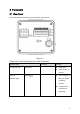
2 Framework
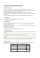
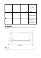
2.1 Rear Panel
This series camera real panel is shown as below. See Figure 2-1.
Figure 2-1
Please refer to the following sheet for detail information.
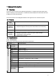
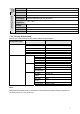
Interface Name Connector Function
AC 24V/ DC 12V Power port z Power port.
z Input 12V DC or
AC 24V
STATUS
Indication Light
Red light z The red light is on
when the system
is working
properly.
z It flashes when
the system is
upgrading.