
Manual

10
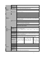
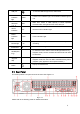
1 Grounding hole
2 Power input port
3 Power button
4 Fan
5 The 1st to the 4th-channel audio input
6 DB25 port (the 5th to the 16th-channel audio input
port)
7 Loop video output
8 Video input
9 Audio output
10 Bidirectional talk input port
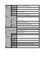
11 Bidirectional talk output port
12 Alarm input/alarm output
13 Video VGA output
14 HDMI port
15 RS-232 port
16 eSATA port
17 USB port
18 Network port
19 Video CVBS output
20 Video matrix output
21 Full-duplex RS-485 port
22 Semi-duplex RS-485 port
When connect the Ethernet port, please use crossover cable to connect the PC and use
the straight cable to connect to the switcher or router.
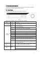
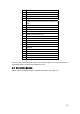
2.3 Connection Sample
Please refer to the following figure for detailed information. See Figure 2-3.