
Owner manual

16
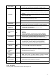
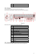
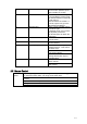
Figure 2-6
Please refer to the following sheet for detailed information.
1 GND port
2 1
st
to 4
th
-channel audio input
3 DB25 port ( 5
th
to 16
th
-channel audio input
port )
4 Audio output
5 Bidirectional talk input port
6 Bidirectional talk output port
7 Alarm input/Alarm output/RS485 port
8 Network port
9 HDMI port
10 RS232 port
11 eSATA port
12 USB port
13 Video VGA output
14 Video input
15 Video output
16 Matrix video output
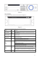
When connect the Ethernet port, please use crossover cable to connect the PC and use the
straight cable to connect to the switcher or router.
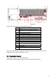
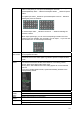
2.3 Connection Sample
Please refer to Figure 2-7 for connection sample.
Please note the following figure is based on the 32-channel 2U series product.