
Owner manual

15
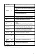
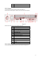
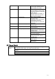
12 Bidirectional talk input port
13 Power on/off button
14 GND port
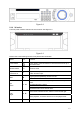
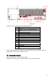
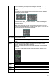
2.2.2 2U series
This series DVR rear panel is shown as below. See Figure 2-5.
Please note the following figure is based on the 24/32-channel series product.
Figure 2-5
Please refer to the following sheet for detailed information.
1 GND port
2 Power input port
3 Power button
4 Fan
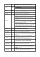
5 1
st
to 4
th
-channel audio input
6 DB25 port ( 5
th
to 16
th
-channel audio input port)
7 Video input
8 Video CVBS output
9 Matrix video output
10 Audio output
11 Bidirectional talk input port
12 Bidirectional talk output port
13 Alarm input/Alarm output/RS485 port
14 Network port
15 HDMI port
16 RS232 port
17 eSATA port
18 USB port
19 Video VGA output
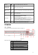
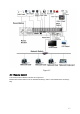
2.2.3 3U series
The 64-channel series DVR rear panel is shown as below. See Figure 2-6.