
Manual

24
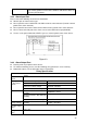
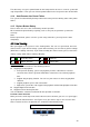
Figure 3-1
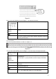
Please refer to the following sheet and Figure 3-1 for detailed information.
1,2,3,4,5,
6,7,8.and the first
line from the left to
the right : 9,10,
11,12,13,14,
15,16
ALARM 1 to ALARM 16. The alarm becomes active in low voltage.
NO1 C1,
NO2 C2,
NO3 C3,
There are three groups of normal open activation output (on/off
button)
Earth cable.
485 A/B
485 communication port. They are used to control devices such as
PTZ. Please parallel connect 120TΩ between A/B cables if there are
too many PTZ decoders.
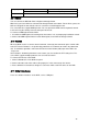
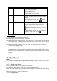
3.8.1.2 2U Series
The 2U series product interface is shown as in Figure 3-2.
Figure 3-2
You can refer to the following sheet and Figure 3-2 for alarm input and output information.
1,2,3,4,, 5, 6, 7,
8, 9, 10, 11, 12, 13,
14, 15, 16
ALARM 1 to ALARM 16. The alarm becomes active in low voltage.
NO1 C1,
NO2 C2,
NO3 C3,
NO4 C4,
NO5 C5 NC5
The first four are four groups of normal open activation output
(on/off button)
NO5 C5 NC5 is a group of NO/NC activation output (on/off button)
CTRL 12V
Control power output. You need to close the device power to cancel
the alarm.
+12V
It is external power input. Need the peripheral equipment to provide
+12V power (below 1A).
Earth cable.
T+, T-, R+, R-
Four-wire full-duplex RS485 port.
T+, T- is the output cable and R+, R- is the input cable.
AB cable
connection