Mobile Network Video Recorder User’s Manual V 1.0.
Table of Contents 1 2 3 Features and Specifications ...............................................................................................................1 1.1 Overview ........................................................................................................................................1 1.2 Function .........................................................................................................................................1 1.3 Features........................
4.2 Navigation Bar ............................................................................................................................22 4.3 Right Click Menu ........................................................................................................................23 4.4 Main Menu...................................................................................................................................23 4.5 Search & Playback ..............................................
.7.9 Display ..................................................................................................................................65 4.7.10 Default ...................................................................................................................................66 4.7.11 Remote Device ....................................................................................................................67 4.7.11.1 UPNP ..............................................................
6.2.1 6.2.2 6.2.3 6.2.4 6.2.5 Monitor Channel Menu Tree ..............................................................................................92 System Menu .......................................................................................................................94 Monitor Window Switch ......................................................................................................94 PTZ Control .....................................................................................
.8 Log out .......................................................................................................................................140 7 Digital Surveillance System ............................................................................................................141 8 FAQ ....................................................................................................................................................142 9 Appendix A HDD Capacity Calculation ................
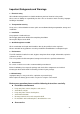
Welcome Thank you for purchasing our network video recorder! This user’s manual is designed to be a reference tool for your system. Please open the accessory bag to check the items one by one in accordance with the list below. Contact your local retailer ASAP if something is missing or damaged in the bag.
Important Safeguards and Warnings 1. .Electrical safety All installation and operation here should conform to your local electrical safety codes. We assume no liability or responsibility for all the fires or electrical shock caused by improper handling or installation. 2. .Transportation security Heavy stress, violent vibration or water splash are not allowed during transportation, storage and installation. 3. .Installation Keep upwards. Handle with care.
Check the following accessories after opening the box: Please refer to the packing list in the box * viii
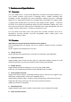
1 Features and Specifications 1.1 Overview This series mobile NVR is a high-end HD digital video surveillance management product. This series product integrates image process technology, wireless network technology, GPS technology, structure technology and vehicle information sampling and process technology together. It uses strong aluminum alloy case and adopts two 2.5-inch HDDs as the storage media. It supports built-in 3G, WIFI wireless transmission mode and GPS module(optional).
Several relay alarm outputs to realize alarm activation and on-site light control. The alarm input port and output port has the protection circuit to guarantee device safety. Communication port RS485 port can realize alarm input and PTZ control. RS232 port can connect to keyboard to realize central control, and can also connect to PC COM to upgrade system and realize maintenance, and matrix control. Standard Ethernet port can realize network access function. PTZ control Support PTZ decoder via RS485.
status. 1.3 Features Adopt dual-HDD as storage media to enhance record save period. Aluminum alloy case, small and sound ventilation, high stability. Built-in power module, convenient installation. Support PoE, can supply power to the network camera directly. Abundant functions, support various alarm mode, record mode and support multiple information, vehicle status sampling and record function. Built-in 3G, WIFI wireless transmission module, and GPS module. Support TV/VGA dual-output. 1.
RS232 Port(RS-422) One RS232 port to debug and transmit COM data. RS485 port(RS-485) One RS485 port to control external PTZ and etc. Support various protocols. USB2.0 Port 2 peripheral USB2.0 ports. Network Connection One RJ45 10/100/1000Mbps self-adaptive Ethernet port. GPS(Optional) Built-in GPS module. Realize GPS information display, aencode overlay, and record. Support GPS time synchronization. Please note only the unit of GPS module supports GPS function.
2 Front Panel and Rear Panel 2.1 Front Panel The front panel is shown as in Figure 2-1. Figure 2-1 Please refer to the following sheet for detailed information. SN Function 1 Power indicator light 2 The red light is on when there is HDD. The light is off when there is no HDD. 3 Network camera connection status indicator light. The light becomes on when the connected network camera is abnormal. 4 Alarm indicator light. 5 HDD storage indicator light.
9 WIFI indicator light Please note only the unit of WIFI module supports this function. 10 Remote control IR receiver 11 Lock button 12 RJ45 network port 13 USB2.0 port 14 eSATA port 2.2 Rear Panel The rear panel is shown as in Figure 2-2. Figure 2-2 Please refer to the following sheet for front panel button information. SN Function 1 3G antenna port Please note only the unit of 3G module supports this function.
6 VGA port 7 Network camera port. Connect to network camera, router and etc. 8 Device power input port. 9 SIM card socket 10 Alarm input/output port 11 GPS aport Please note only the unit of GPS module supports this function. 12 Extension port 13 Bidirectional talk port Extension Port The extension port is shown as in Figure 2-3. Figure 2-3 Please refer to the following sheet for detailed information.
Figure 2-1 Serial Number Name Function 1 View Switch window 2 ID Click it to input device serial number, so that you 3 Number 0 to 9 can control it. Input password, channel or switch channel. 4 Record 5 Aux Auxiliary button 6 Enter Confirm button Menu Menu button Esc Cancel button Record ⊳ 7 Direction buttons Direction buttons in PTZ. Control. Stop button Zoom out button in the PTZ control.
│ Next Various fats play speeds and normal play speed. Focus (+) button in the PTZ control. 8 F1 Shortcut button to backup 9 F2 Reserved for future use. 10 F3 Reserved for future use. 2.4 Mouse Operation Please refer to the following sheet for mouse operation instruction. Left click mouse When you have selected one menu item, left click mouse to view menu content. Modify checkbox or motion detection status. Click combo box to pop up dropdown list In input box, you can select input methods.
button Page up or page down Move mouse Select current control or move control Drag mouse Select motion detection zone Select privacy mask zone.
3 Installation Installation and Connections Note: All the installation and operations here should conform to your local electric safety rules. 3.1 Check Unpacked NVR When you receive the NVR from the forwarding agent, please check whether there is any visible damage. The protective materials used for the package of the NVR can protect most accidental clashes during transportation. Then you can open the box to check the accessories.
Figure 3-2 3) Now you can install the first HDD. Please turn the HDD bracket up. See Figure 3-3. Put the HDD to the HDD bracket along the arrow direction. Line up the holes of the HDD to the HDD secure holes. Use bolts to secure the HDD. Figure 3-3 4)Install the second HDD. Please refer to Figure 3-4 to put the second HDD to the HDD bracket.
Line up the holes of the top of the HDD to the rear panel of the HDD bracket. Use bolts to secure the HDD. You can kip to the next step if there is only one HDD on the box. Figure 3-4 5) Now you can install HDD bracket. After you install the HDD(s), put the HDD bracket to the HDD box and secure the two bolts of the HDD bracket. See Figure 3-5. Figure 3-5 6) After you installed the HDD bracket, put the HDD box top cover back and secure the bolts of the HDD box. Now the HDD installation is complete.
3.4 Connecting Power Supply Please check input voltage and device power button match or not. We recommend you use UPS to guarantee steady operation, NVR life span, and other peripheral equipments operation such as cameras. 3.5 Connecting Video Input and Output Devices System adopts standard RJ45 network port to input audio/video data. 3.5.1 Connecting Video Output Video output includes a CVBS(PAL/NTSC BNC(1.0VP- P, 75Ω)output and a VGA output. System supports CVBS and VGA output at the same time.
Please refer to the following sheet for detailed information. SN Function 1 12V external camera power. It is less than 1.5A. 2 GND 3 Audio port 4 Video port Audio/video output cable is shown as below. See Figure 3-7. You can use it when your monitor port is general BNC port. Figure 3-7 Please refer to the following sheet for detailed information.
c. When the alarm device is connecting one NVR and one other device, please use a relay to separate them, 2. Alarm output The alarm output port should not be connected to high power load directly (It shall be less than 1A) to avoid high current which may result in relay damage. Please use the co contactor to realize the connection between the alarm output port and the load. 3. How to connect PTZ decoder a. Ensure the decoder has the same grounding with NVR, otherwise you may not control the PTZ.
16 GND 17/18 PTZ control cable AB cable. Bidirectional talk port interface is shown as in Figure 3-9. Figure 3-9 Please refer to the following sheet for detailed information. 3.6.2 SN Function 1 12V/1A 2 GND 3 MIC IN 4 MIC OUT 5/6 Speaker+, speaker- Alarm Input Port Please refer to the following sheet for more information. See Figure 3-10. Normal open or Normal close type.
3.6.3 Alarm Output Port 2 ways relay alarm output (NO contact). Provide external power to external alarm device. To avoid overloading, please read the following relay parameters sheet carefully. RS485 A/B cable is for the A/B cable of the PTZ decoder. Relay Specification Model: HFD23 Contact Contact mode 1Z Parameter Contact resistance 100mΩ(0.1A 6VDC) Contact material AgNi+gold-plating Contact 0.
Loop Seal mode Sealed Rated Loop Power Standard mode:200mW; Sensitivity mode: 150mW Please note the number in the above sheet is the initial value.
4 GUI Operation Connect the device to the monitor and then connect a mouse and power cable. Click the power button at the rear panel and then boot up the device to view the analog video output. You can use the mouse to implement some GUI operation. 4.1 Login Login After device booted up, the system is in multiple-channel display mode. See Figure 4-1. Figure 4-1 Right click mouse, you can see login interface. See Figure 4-2. System consists of four accounts: Username: admin. Password: admin.
You can overlay the corresponding date, time and channel name on each screen. You can refer to the following sheet for channel record or alarm status information. 1 Recording status 3 Video loss 2 Motion detection 4 Camera lock Preview Control The preview control function has the following features. Support preview playback. In the preview desktop, system can playback previous 5-60 minutes record of current channel. Please go to the Main Menu->General to set real-time playback time.
video of multiple-channel at the same time. Current selected backup channel has an icon as and the free channel is shown as an icon as . Once the backup started, you can see the free channel is shown as an icon as . 4 Manual Snap Click it to snap manually. 5 Remote device add shortcut It is to go to the remote device connection interface. 6 Exit Playback control The playback control has the following features. Support play, pause, and exit and drag function.
detailed information. ⑦HDD Manager: It is the HDD manager shortcut button. Please refer to chapter4.8.1 for detailed information. 4.3 Right Click Menu After you logged in the device, right click mouse, you can see the short cut menu. Please see Figure 4-5. Here you can set local playback window, PTZ control, video color, search records, remote device and etc. The local playback window includes 1/4. Figure 4-5 4.4 Main Menu After you logged in, the system main menu is shown as below. See Figure 4-6.
2 1 3 4 11 5 7 6 10 8 12 9 Figure 4-7 Please refer to the following sheet for more information. SN Name Function Display window Search type Here you can select to search the picture or the recorded file. You can select to play from the read-write HDD, from peripheral device or from redundancy HDD. Before you select to play from the peripheral device, please connect the corresponding peripheral device. You can view all record files of the root directory of the peripheral device.
Double click it, you can view the picture/record file list of current day. The file list is to display the first channel of the record file. The system can display max 128 files in one time. Use the / or the mouse to view the file. Select one item, and then double click the mouse or click the ENTER button to playback. You can input the period in the following interface to begin accurate search. File type:R—regular record; A—external alarm record;M—Motion detect record.
Fast forward In playback mode, click to realize various fast play modes such as fast play 1,fast play 2 and etc. Note: The actual play speed has relationship with the software version. Smart search The volume of the playback 8 9 10 Time bar Click the snapshot button in the full-screen mode, the system can snapshot 1 picture per second. System supports custom snap picture saved path. Please connect the peripheral device first, click snap button on the full-screen mode, you can select or create path.
13 Other channel synchronization switch to play when playback 14 Other channel synchronization switch to play when playback When playing the file, click the number button, system can switch to the same period of the corresponding channel to play. Digital zoom When the system is in full-screen playback mode, left click the mouse in the screen. Drag your mouse in the screen to select a section and then left click mouse to realize digital zoom. You can right click mouse to exit.
○ means current HDD is normal.. - means there is no HDD. If disk is damaged, system shows as “?”. Please remove the broken hard disk before you add a new one. Figure 4-9 In Figure 4-9, click view record d time button, HDD record time information interface is shown as in Figure 4-10. Figure 4-10 Parameter Function SATA 1-2 here means there are 2 HDDS. When HDD is working properly, system is shown as O. . “_” means there is no HDD.
SN You can view the HDD amount the device connected to; ﹡ means the second HDD is current working HDD. Type The corresponding HDD property. Total space The HDD total capacity. Free space The HDD free capacity. Status HDD can work properly or not. Bad track Display there is bad track or not. Page up Click it to view previous page. Page down Click it to view the next page. View recording time Click it to view HDD record information (file start time and end time).
Start time/end time: Pleased select start time and end time, then click search button. You can view the log files in a list. System max displays 100 logs in one page. It can max save 1024 log files. Please use page up/down button on the interface or the front panel to view more. Backup: Please select a folder you want to save; you can click the backup button to save the log files. After the backup, you can see there is a folder named Log_time on the backup path.
Alarm in Alarm out System version: Build Date Web Serial number Figure 4-14 4.6.5 Online Users Here is for you manage online users connected to the local device. See Figure 4-15. You can disconnect one user or block one user if you have proper system right. You can max block for 65535 seconds. Figure 4-15 4.6.6 Remote Device Information Here you can view the channel status of the remote device, connection log and etc.
Figure 4-16 Connection log: In this interface, you can search the IPC log information of the corresponding channel. It includes IPC online, offline and etc. See Figure 4-17. Figure 4-17 4.6.7 GPS Log Here you can view device GPS log information and save GPS information to HDD as one file. See Figure 4-18.
Figure 4-18 4.6.8 Network Info In this interface, you can see network test and network load information. 4.6.8.1 Network Test Network test interface is shown as in Figure 4-19. Destination IP: Please input valid IPV4 address and domain name. Test: Click it to test the connection with the destination IP address. The test results can display average delay and packet loss rate and you can also view the network status as OK, bad, no connection and etc. Network Sniffer backup: Please insert USB2.
Figure 4-19 4.6.8.2 Network Load Network load is shown as in Figure 4-20. Here you can view the follow statistics of the device network adapter. Here you can view information of all connected network adapters. The connection status is shown as offline if connection is disconnected. Click one network adapter, you can view the flow statistics such as send rate and receive rate at the top panel Figure 4-20 4.7 Setting In main menu, highlight setting icon and double click mouse.
below. See Figure 4-21. Figure 4-21 Important Please note you need to have the proper right to implement the following operation. 4.7.1 General General setting includes the following items. See Figure 4-22. System time: Here is for you to set system time Date format: There are three types: YYYYY-MM-DD: MM-DD-YYYYY or DD-MM-YYYY. Date separator: There are three denotations to separate date: dot, beeline and solidus. DST: Here you can set DST time and date.
Plate No: Here you can set vehicle plate number. Holiday setting: Click it you can see an interface shown as in Figure 4-25. Here you can set holiday date. Please go to the Holidays Period interface to set the holiday date record setup. When you enable Holiday settings and schedule setup at the same time, holiday setting has the priority. If the selected day is a holiday, then system records as you set in holiday setting. If it is not a holiday, system records as you set in Schedule interface.
Figure 4-23 Figure 4-24 Figure 4-25 Figure 4-26 4.7.2 Encode Encode setting includes the following items. See Figure 4-27. Please note some series do not support extra stream. Channel: Select the channel you want. Type: Please select from the dropdown list. There are three options: regular/motion detect/alarm. You can set the various encode parameters for different record types. Compression: System supports H.264, MPEG4, MJPEG and etc.
Bit rate type: System supports two types: CBR and VBR. In VBR mode, you can set video quality. Quality: There are six levels ranging from 1 to 6. The sixth level has the highest image quality. Video/audio: You can enable or disable the video/audio. The main stream is enabled by default. The record includes audio and video if you highlight audio button here. For extra stream, you need to check video first and then select audio. Audio format: Here you can set device audio format.
Figure 4-27 Figure 4-28 Figure 4-29 4.7.3 Schedule In the main menu, from setting to schedule, you can go to schedule menu. See Figure 4-30. Channel: Please select the channel number first. You can select “all” if you want to set for the whole channels. Week day: There are eight options: ranges from Saturday to Sunday and all.
Pre-record: System can pre-record the video before the event occurs into the file. The value ranges from 1 to 30 seconds depending on the bit stream. Redundancy: System supports redundancy backup function. It allows you backup recorded file in two disks. You can highlight Redundancy button to activate this function. Please note, before enable this function, please set at least one HDD as redundant. (Main menu->Advanced->HDD Management). Please note this function is null if there is only one HDD.
Stop bit: There are three values: 1/1.5/2. Parity: there are five choices: none/odd/even/space mark. System default setup is: Function: Console Baud rate:115200 Data bit:8 Stop bit:1 Parity: None After completing all the setups please click save button, system goes back to the previous menu. Figure 4-31 4.7.5 Network Here is for you to input network information. See Figure 4-32. IP Version: There are two options: IPv4 and IPv6.
view current IP information. Besides, when PPPoE is operating, you can not modify IP/Subnet mask /Gateway. TCP port: Default value is 37777. You can change if necessary. UDP port: Default value is 37778. You can change if necessary. HTTP port: Default value is 80. RTSP port: Default value is 554. Important: System needs to reboot after you changed and saved any setup of the above four ports. Please make sure the port values here do not conflict. Max connection: system support maximal 20 users.
Figure 4-33 4.7.5.2 IP Filter IP filter interface is shown as in Figure 4-34. You can add IP in the following list. The list supports max 64 IP addresses. System supports valid address of IPv4 and IPv6. Please note system needs to check the validity of all IPv6 addresses. After you enabled trusted sites function, only the IP listed below can access current NVR. If you enable blocked sites function, the following listed IP addresses can not access current NVR.
Edit: Click it to edit start address and end address. System can check the IP address validity after the edit operation and implement IPv6 optimization. Figure 4-34 4.7.5.3 NTP Setup You need to install SNTP server (Such as Absolute Time Server) in your PC first. In Windows XP OS, you can use command “net start w32time” to boot up NTP service. NTP setup interface is shown as in Figure 4-35. Host IP: Input your PC address. Port: This series NVR supports TCP transmission only.
Atlantic Time GMT-4 Brazil GMT-3 Middle Atlantic Time GMT-2 Figure 4-35 4.7.5.4 Multicast Multiple-cast setup interface is shown as in Figure 4-36. Figure 4-36 Here you can set a multiple cast group. Please refer to the following sheet for detailed information. IP multiple cast group address -224.0.0.0-239.255.255.255 -“D” address space The higher four-bit of the first byte=”1110” Reserved local multiple cast group address -224.0.0.0-224.0.0.
Used for multiple cast broadcast in limited space. Except the above mentioned addresses of special meaning, you can use other addresses. For example: Multiple cast IP: 235.8.8.36 Multiple cast PORT: 3666. After you logged in the Web, the Web can automatically get multiple cast address and add it to the multiple cast groups. You can enable real-time monitor function to view the view. Please note multiple cast function applies to special series only. 4.7.5.5 PPPoE PPPoE interface is shown as in Figure 4-37.
Figure 4-38 Please note NNDS type includes: CN99 DDNS, NO-IP DDNS, Quick DDNS, and Dyndns DDNS. All the DDNS can be valid at the same time, you can select as you requirement. Quick DDNS function shall work with special DDNS server and special Professional Surveillance Software (PSS). Quick DDNS and Client-end Introduction 1) Background Introduction Device IP is not fixed if you use ADSL to login the network. The DDNS function allows you to access the NVR via the registered domain name.
Do not register frequently. The interval between two registrations shall be more than 60 seconds. Too many registration requests may result in server attack. System may take back the domain name that is idle for one year. You can get a notification email before the cancel operation if your email address setup is OK. 4.7.5.7 UPNP The UPNP protocol is to establish a mapping relationship between the LAN and the WAN. Please input the router IP address in the LAN in Figure 4-32.
Figure 4-39 Figure 4-40 4.7.5.8 WIFI You can view the WIFI connection status in the Network Setting interface. See Figure 4-41. You can view current connection status and IP address if there is a connection.
The WIFI interface is shown as below. See Figure 4-42. Auto connect WIFI: Check the box here, system automatically connects to the previous WIFI hotspot. Refresh: You can click it to search the hotspot list again. It can automatically add the information such as the password if you have set it before. Disconnect: Here you can click it to turn off the connection. Connect: Here you can click it to connect to the hotspot.
Figure 4-44 WIFI working status: Here you can view current connection status. Please note: After successful connection, you can see WIFI connection icon at the top right corner of the preview interface. When the hotspot verification type is WEP, system displays as AUTO since the device can not detect its encryption type. System does not support verification type WPA and WPA2. The display may become abnormal for the verification type and encryption type.
Title: Please input email subject here. System support English character and Arabic number. Max 32-digit. Receiver: Please input receiver email address here. System max supports 3 email boxes. SSL enable: System supports SSL encryption box. Interval: The send interval ranges from 0 to 3600 seconds. 0 means there is no interval. Health email enable: Please check the box here to enable this function. This function allows the system to send out the test email to check the connection is OK or not.
Please install Ser-U FTP SERVER first. From “start” -> “program” -> Serv-U FTP Server -> Serv-U Administator. Now you can set user password and FTP folder. Please note you need to grant write right to FTP upload user. See Figure 4-48. Figure 4-48 You can use a PC or FTP login tool to test setup is right or not. For example, you can login user ZHY to FTP://10.10.7.7 and then test it can modify or delete folder or not. See Figure 4-49.
After completed channel and weekday setup, you can set two periods for one each channel. Click the Test button, you can see the corresponding dialogue box to see the FTP connection is OK or not. See Figure 4-51. Figure 4-50 Figure 4-51 4.7.5.11 Alarm center Interface is pre-reserved for the users to develop this function. 4.7.5.12 SNMP SNMP is an abbreviation of Simple Network Management Protocol. It provides the basic network management frame of the network management system.
Figure 4-52 Please enable the SNMP function. Use the corresponding software tool (MIB Builder and MG-SOFT MIB Browser. You still need two MIB file: BASE-SNMP-MIB, NVR-SNMP-MIB) to connect to the device. You can get the device corresponding configuration information after successfully connection. Please follow the steps listed below to configure. In Figure 4-52, check the box to enable the SNMP function. Input the IP address of the PC than is running the software in the Trap address.
Figure 4-53 2) The proxy server software developed from the SDK. Please open the software and input the global setup. Please make sure the auto connection port here is the same as the port you set in the previous step. 3) Now you can add device. Please do not input default port number such as the TCP port in the mapping port number. The device ID here shall be the same with the ID you input in Figure 4-53. Click Add button to complete the setup. 4) Now you can boot up the proxy server.
for the work day/free day setup and the specific work day setup, system just saves the latest setup. For example, the work day ranges from 8:30-17:30 Monday to Friday, and then you set the period 7:10-18:00 for Monday. So, the arm period of the Monday ranges from 7:10 to 18:00. Please highlight the corresponding button to enable this function. PTZ activation: When an alarm occurred, system can activate the PTZ operation such as preset x. Anti-dither: Here you can set anti-dither time.
begins the alarm record instead of the MD record if the local alarm and MD event occurred at the same time. Tour: Here you can enable tour function when an alarm occurs. System supports 1/8-window tour. Please go to chapter 4.7.9 Display for tour interval setup. Please note the tour setup here has higher priority than the tour setup you set in the Display interface. Once there two tours are both enabled, system can enable the alarm tour as you set here when an alarm occurred.
Figure 4-56 Figure 4-57 4.7.7 Detect Go to Detect Menu In the main menu, from Setting to Detect, you can see motion detect interface. See Figure 4-58.There is three detection types: motion detection, video loss, camera masking. The video loss has no detection region and sensitivity setup and camera masking has no detection region setup. You can see motion detect icon if current channel has enabled motion detect alarm. You can drag you mouse to set motion detect region without Fn button.
Period: Click set button, you can see an interface is shown as in Figure 4-61. Here you can set for business day and non-business day. In Figure 4-61 click set button, you can see an interface is shown as in Figure 4-62. Here you can set your own setup for business day and non-business day. Alarm output: when an alarm occurs, system enables peripheral alarm devices. Latch: when motion detection complete, system auto delays detecting for a specified time.
Figure 4-58 Figure 4-59 Figure 4-60 61
Figure 4-61 Figure 4-62 4.7.7.2 Video Loss In Figure 4-58, select video loss from the type list. You can see the interface is shown as in Figure 4-63.This function allows you to be informed when video loss phenomenon occurred. You can enable alarm output channel and then enable show message function. You can refer to chapter 4.7.7.1Motion detect for detailed information. Tips: You can enable preset/tour/pattern activation operation when video loss occurs.
4.7.7.3 Camera Masking When someone viciously masks the lens, or the output video is in one-color due to the environments light change, the system can alert you to guarantee video continuity. Camera masking interface is shown as in Figure 4-64. You can enable alarm output channel and then enable show message function. You can refer to chapter 4.7.7.1Motion detect for detailed information. Tips: You can enable preset/tour/pattern activation operation when video loss occurs.
In the main menu, click setting, and then click Pan/Tilt Control button. The interface is shown as in Figure 4-65. Here you can set the following items: Channel: Select the current camera channel. PTZ type: There are two types: local/remote. Protocol: Select corresponding PTZ protocol(such as PELCOD) Address: Default address is 1. Baud rate: Select corresponding baud rate. Default value is 9600. Data bit: Select corresponding data bits. Default value is 8.
key in the remote control). Click Pan/Tilt/Zoom, the interface is shown as below. See Figure 4-67. Here you can set the following items: Step: value ranges fro 1 to 8. Zoom Focus Iris Please click icon and to adjust zoom, focus and iris. Figure 4-67 In Figure 4-67, please click direction arrows to adjust PTZ position. There are total 8 direction arrows. Figure 4-68 Here is a sheet for you reference. Name Function key function Zoom Wide Focus Near Iris Close 4.7.
Interval: Input proper interval value here. The value ranges from 5-120 seconds. In tour process, you can use mouse or click Shift to turn on window switch function. Stands for opening switch function, stands for closing switch function. Motion tour type: System supports 1 window tour. Alarm tour type: System supports 1 window tour. Please highlight icon to select the corresponding function. After completing all the setups please click save button, system goes back to the previous menu.
Schedule RS232 Network Alarm Detect Pan/tilt/zoom Display Channel name Remote device Please highlight icon to select the corresponding function. See Figure 4-71. After all the setups please click OK button, system goes back to the previous menu. Figure 4-71 Warning! System menu color, language, time display mode, video format, IP address, user account will not maintain previous setup after default operation! 4.7.
Figure 4-72 4.7.11.3 Remote Device In the main menu, click the Remote Device icon to go to the corresponding interface. See Figure 4-73. Figure 4-73 The remote device interface is shown as in Figure 4-74. IP search: Click it to search IP address. Add: Click it to connect to the selected device and add it to the Added device list. Support Batch add. Show filter: You can use it to display the specified devices from the added device. Edit: Please refer to manual add button.
BLC: Check the box here to enable backlight compensation function. System can automatically expose according to environment so that you can view the darkest section of the video. Day/Night mode: Here is to set video color or black and white mode. a) Color: Camera only outputs color video. b) Auto: Camera auto selects color or black and white video according to device feature (Video whole brightness or there is any IR light or not.). c) Black and white: Camera only outputs black and white video.
Figure 4-75 Click the Manual Add button; you can go to the following interface. See Figure 4-76. It can max supports 4-channel standard definition network camera, or 4-channel 720P network camera or 4-channel 1080P network camera. This series product supports the network camera from many popular manufactures such as Sony, Hitachi, dynacolor, Axis, Samsung, arecont, Dahua, onvif and custom type. You can just input URL address, user name, and password to login the front-end device.
4.7.11.4 Short-cut Menu In the preview interface, for the channel of no IPC connection, you can click the icon “+” in the centre of the interface to quickly go to the Remote Device interface. See Figure 4-77 and Figure 4-78. Figure 4-77 Figure 4-78 4.8 Advanced Double click advanced icon in the main window, the interface is shown as below. See Figure 4-79.
Figure 4-79 4.8.1 HDD Management Here is for you to view and implement hard disk management. See Figure 4-80. You can see current HDD type, status, capacity and record time. When HDD is working properly, system is shown as O. When HDD error occurred, system is shown as X. Alarm set: Click alarm set button, the interface is shown as below. See Figure 4-81. (This interface is just like the abnormality setup). Please refer to chapter 4.8.2 for detailed information.
Figure 4-81 For the HDD group setup operation, please note: Each channel’s records can be stored into the specified HDD Group. Each HDD Group is corresponding to several hard disks, while one hard disk is only included in one HDD Group. Each channel is only corresponding with one HDD Group, while one HDD Group can store records from several channels. HDD Group is only available for read-write HDD and self-defined disks, other types of hard disks cannot be set as HDD Group.
Figure 4-82 Channels Setting Click the button named with “Channels Settings” in Figure 4-80, system will pop up an interface shown as in Figure 4-83. You can set HDDs for main stream, extra stream and snap pictures respectively. The main stream and extra stream of one channel can be saved to different groups. Channel: It is to display the actual channel number of current NVR. HDD Group: It is the SN of the HDD group management.
4.8.2 Abnormality Abnormality interface is shown as in Figure 4-84. Event type: There are several options for you such as disk error, no disk, no space, disconnection, IP conflict and etc (multiple choices). Alarm output: Please select alarm activation output port (multiple choices). Latch: Here you can set corresponding delaying time. The value ranges from 1s-300s. System automatically delays specified seconds in turning off alarm and activated output after external alarm cancelled.
4.8.4 Manual Record Note: You need to have proper rights to implement the following operations. Please make sure the HDD has been properly installed. 4.8.4.1 Manual record menu Right click mouse or in the main menu, Advanced->Manual Record. Manual record menu is shown as in Figure 4-86. 4.8.4.2 Basic operation There are two streams: main stream/extra stream. There are three statuses: schedule/manual/stop. Please highlight icon“○” to select corresponding channel. Manual: The highest priority.
Figure 4-87 4.8.4.4 Enable all channel recording Highlight ○ below All, you can enable all channel recording. All channel schedule record Please highlight “ALL” after “Schedule”. See Figure 4-88. When system is in schedule recording, all channels will record as you have previously set (Main menu->Setting->Schedule). The corresponding indication light in front panel will turn on. Figure 4-88 All channel manual record Please highlight “ALL” after “Manual.” See Figure 4-89.
Figure 4-89 4.8.4.5 Stop all channel recording Please highlight “ALL” after “Stop”. See Figure 4-90. System stops all channel recording no matter what mode you have set in the menu (Main menu->Setting->Schedule) Figure 4-90 4.8.5 Account Here is for you to implement account management. See Figure 4-91. Here you can: Add new user Modify user Add group Modify group Modify password.
middle. The string includes the valid character, letter, number, underline, subtraction sign, and dot. System account adopts two-level management: group and user. No limit to group or user amount. For group or user management, there are two levels: admin and user. The user name and group name can consist of eight bytes. One name can only be used once. There are four default users: admin/888888/666666 and hidden user “default”. Except user 6666, other users have administrator right.
Figure 4-92 4.8.5.2 Add/Modify Group Click add group button, the interface is shown as below. See Figure 4-93. Here you can input group name and then input some memo information if necessary. There are total 60 rights such as control panel, shut down, real-time monitor, playback, record, record file backup, PTZ, user account, system information view, alarm input/output setup, system setup, log view, clear log, upgrade system, control device and etc. The modify group interface is similar to the Figure 4-93.
Figure 4-94 4.8.6 Auto Maintenance Here you can set auto-reboot time and auto-delete old files, auto shutdown, and auto ACC delay (0-65535 minutes) setup. You can set to delete the files for the specified days. See Figure 4-95. After all the setups please click save button, system goes back to the previous menu. Figure 4-95 4.8.7 Config Backup The configuration file backup interface is shown as below. See Figure 4-96. This function allows you to copy current system configuration to other devices.
Figure 4-96 4.8.8 Vehicle Setting Here you can view or set vehicle gravity sensor. See Figure 4-97. Figure 4-97 Double click gravity sensor, you can view the gravity acceleration. See Figure 4-98.
Figure 4-98 4.9 Backup NVR supports USB burner, flash disk, portable HDD, eSATA HDD (Need external power supplying and does not support hot swap). Here we introduce USB backup. You can refer to Chapter 6 Web Operation for network download backup operation. 4.9.1 Detect Device Click backup button, you can see an interface is shown as in Figure 4-99. Here is for you to view device information. You can view backup device name and its total space and free space. Figure 4-99 4.9.
Select backup device and then set channel, file start time and end time. Click add button, system begins search. All matched files are listed below. System automatically calculates the capacity needed and remained. See Figure 4-100. Figure 4-100 System only backup files with a √ before channel name. You can use AUX button to check or cancel file. Click backup button, you can backup selected files. There is a process bar for you reference. See Figure 4-101. Click backup button, system begins burning.
4.9.3 One key backup Insert backup device to the USB port at the front panel and click the F1 button of the remote control, system automatically backup current record files to the device. 4.10 Shutdown Double click shutdown button, system pops up a dialogue box for you to select. See Figure 4-102. Logout menu user: log out menu. You need to input password when you login the next time. Restart application: reboot device. Shutdown: system shuts down and turns off power.
5 Quick Configuration Tool 5.1 Overview Quick configuration tool can search current IP address, modify IP address. At the same time, you can use it to upgrade the device. Please note the tool only applies to the IP addresses in the same segment. 5.2 Operation Double click the “ConfigTools.exe” icon, you can see an interface is shown as in Figure 5-1. In the device list interface, you can view device IP address, port number, subnet mask, default gateway, MAC address and etc.
Select the “Open Device Web” item; you can go to the corresponding web login interface. See Figure 5-3. Figure 5-3 If you want to modify the device IP address without logging in the device web interface, you can go to the configuration tool main interface to set. In the configuration tool search interface (Figure 5-1), please select a device IP address and then double click it to open the login interface. Or you can select an IP address and then click the Login button to go to the login interface.
Figure 5-5 For detailed information and operation instruction of the quick configuration tool, please refer to the Quick Configuration Tool User’s Manual included in the resources CD.
6 Web Operation 6.1 General Introduction The device web provides channel monitor menu tree, search, alarm setup, system setup, PTZ control and monitor window. 6.1.1 Preparation Before log in, please make sure: Network connection is right You have set PC IP address, NVR IP address, subnet mask and gateway. (Please set the IP address of the same section for the PC and NVR. Please input corresponding gateway and subnet mask if there are routers.) The default NVR IP address is 192.168.1.108.
or not. If system finds the previous information and the channel is idle, system can map it to the previously used channel. Otherwise system goes to the next step. c) Thirdly, according to the --- map, system can know the previous mapping channel of current PoE port. System can select current channel if it is free. Otherwise, it goes to the next step: d) Fourthly, system goes to find the first idle channel it can get.
Figure 6-2 IE Safety Setup After installation, the interface is shown as below. See Figure 6-3. Figure 6-3 Login interface Please input your user name and password. Default factory name is admin and password is admin. Note: For security reasons, please modify your password after you first login. 6.
②②②② For the LAN mode, after you logged in, you can see the main window. See Figure 6-4. ③③③③ ④④④④ ①①①① ⑤⑤⑤⑤ Figure 6-4 Main Interface There are five sections: Section 1: Monitor channel menu tree Section 2: System menu Section 3: PTZ control Section 4: Video setup and other setup Section 5: Monitor window switch 6.2.1 Monitor Channel Menu Tree The monitor channel menu tree is shown as in Figure 6-5.
Figure 6-5 Monitor Channel Menu Tree Please refer to the following sheet for detailed information. Parameter Function CAM 1 to CAM 4 channel 1 to channel 4 Open all /close all Click this button to open all video channels. Once all video channels are open, it becomes close all button. Start Dialogue You can click this button to enable audio talk. Click 【▼】 to select bidirectional talk mode. There are four options: DEFAULT, G711a,G711u and PCM.
Please refer to the following sheet for monitor window parameter information. 6.2.2 Parameter Function Display device information Digital zoom Click this button and then left drag the mouse in the zone to zoom in. Right click mouse system restores original status. Local record When you click local record button, the system begins recording. The recorded file is saved to system folder: \ RecordDownload(default). Snapshot You can snapshoot important video.
chapter 6.4.2.2 PTZ). Here you can view direction keys, speed, zoom, focus, iris, preset, tour, pan, scan, pattern, aux close, and PTZ setup button. Please note: open menu/close menu/up/down/left/right/confirm/cancel buttons are for speed dome only. PTZ direction: PTZ supports eight directions: left/right/up/down/upper left/upper right/bottom left/bottom right. Speed: The step 8 speed is faster than step 1. You can click this icon to display or hide the PTZ control platform.
Figure 6-11 PTZ Setup Please refer to the following sheet for PTZ setup information. Parameter Function Scan Move the camera to you desired location and then click left limit button. Then move the camera again and then click right limit button to set a right limit. Preset Use direction keys to move the camera to your desired location and then input preset value. Click add button, you have set one preset. Tour Input auto tour value and preset value.
Parameter Function Light/wiper You can control the light and wiper of the peripheral device via RS485 (RS-485) command. Please note the peripheral device shall support this function. 6.2.5 Color and More Setup Color and other setup interface are shown as in Figure 6-12. Figure 6-12 Color Please refer to the following sheet for detailed information. Parameter Function Video setup It is to adjust monitor video brightness. It is to adjust monitor video contrast ness.
Record Path Click record path button, system pops up an interface for you to modify path. Reboot Click this button to reboot device. If there is local use logged in the system menu, or the Web logged in user has no right to reboot the device system pops up a dialogue box to alert you. Record format There are two options: DAV, ASF. 6.3 WAN Login In WAN mode, after you logged in, the interface is shown as below. See Figure 6-14.
3) Multiple-channel monitor, system adopts extra stream to monitor by default. Double click one channel, system switches to single channel and system uses main stream to monitor. You can view there are two icon at the left top corner of the channel number for you reference. M stands for main stream. A stands for 4) When you switch from Monitor to Search or Configuration, system pops a dialogue box asking you leave current interface or not. See Figure 6-16.
Figure 6-17 Version Information 6.4.1.2 HDD information Here you can view local storage status such as free capacity and total capacity. See Figure 6-18. Figure 6-18 HDD Information 6.4.1.3 Log Here you can view system log.
Figure 6-19 Log Please refer to the following sheet for log parameter information. Parameter Function Type Log types include: system operation, configuration operation, data management, alarm event, record operation, user management, log clear and file operation. Start time Set time to start search. Finish time Set time to finish search Search You can select log type from the drop down list and then click search button to view the list.
Figure 6-20 General Setup Figure 6-21 DST Figure 6-22 DST Please refer to the following sheet for detailed information. Parameter Function System Time Here is for you to modify system time. Please click Save button after your completed modification Sync PC You can click this button to save the system time as your PC current time.
Data Format Here you can select data format from the dropdown list. Data Separator Please select separator such as – or /. Time Format There are two options: 24-H and 12-H. DST Here you can set day night save time begin time and end time. See Figure 6-21and Figure 6-22. Language Here you can view the system current language. You can select from the dropdown list. HDD Full There are two options: stop recording or overwrite the previous files when HDD is full.
Channel Name Display the current channel ID. You can also modify the channel ID here. Encoding mode The device does not support it. For the main stream, recorded file only contains video by default. You need to draw a circle here to enable audio function. Audio / video For extra stream, you need to draw a circle to select the video first and then select the audio if necessary. Main code stream types are 1080P/720P. Resolution Channel 1~4 extra code stream supports CIF/QCIF.
Figure 6-24 Schedule Figure 6-25 Schedule Time Figure 6-26 Copy 105
Figure 6-27 Please refer to the following sheet for detailed information. Parameter Function Channel Please select a channel first. Pre-record Please input pre-record value here. When alarm record or motion detection record occurs, system can record the several seconds video before activating the record operation into the file. (Depends on data size). Setup In Figure 6-24, click set button, you can go to the corresponding setup interface. See Figure 6-25.
Figure 6-28 RS232 Please refer to the following sheet for detailed information. Parameter Function RS232 There is only one option COM 01, corresponding to RS232. Function Console is for debug. Control keyboard: Switch between RS232 and control keyboard. Network keyboard: COM control protocol. You can use network keyboard to control NVR via COM. Transparent COM: Network user can communicate with RS232 COM device. PTZ matrix: PTZ matrix protocol. You can use the device to control the PTZ matrix.
Figure 6-29 Network Please refer to the following sheet for detailed information. Parameter Function IP Version There are two options: IPv4 and IPv6. Right now, system supports these two IP address format and you can access via them. MAC Address The host in the LAN can get a unique MAC address. It is for you to access in the LAN. It is read-only. IP Address Here you can use up/down button ( ) or input the corresponding number to input IP address.
Figure 6-30 Network Parameter Remote host Function PPPOE Input the user name and password which ISP(Internet service supplier) provided and chose enable. Reboot system after configuration is saved and the device will auto connect to Internet. The IP address is the WAN IP. There are two conditions for reboot, 1. The user must have the authority to reboot device. 2.
Please refer to the following sheet for detailed information. Parameter Function SMTP Server Input server address and then enable this function. You can also input the corresponding server domain name here, but you need to go to DNS interface (chapter 7.3.4.1) to set the server IP that can parse the domain. SSL enable You can enable SSL encryption function to guarantee data safety. Port Default value is 25. You can modify it if necessary. User Name The sender email account user name.
Parameter Function Server Port DDNS server port. Domain Name Your self-defined domain name. User The user name you input to log in the server. Password The password you input to log in the server. Interval Device sends out alive signal to the server regularly. You can set interval value between the device and DDNS server here. Private DDNS and Client-end Introduction 1) Background Introduction Device IP is not fixed if you use ADSL to login the network.
Figure 6-33 NAS Figure 6-34 NAS Setup Please refer to the following sheet for detailed information. Parameter Function NAS enable Please select network storage protocol and then enable NAS function. The network storage protocol includes FTP. Server IP Input remote storage server IP address. Port Input Remote storage server port number. User Name Log in user account. File length The max files length when you transfer the file. When the input value is 0, then system upload the whole files.
Parameter Function Remote Path Remote storage file path. Channel Period info. Select a monitor channel. In NAS interface, click set button, you can go to the corresponding setup interface. See Figure 6-34. .Please set schedule period and then select corresponding record type: schedule/alarm. Please note device does not support motion detect record function now. Please select date (Current setup applies to current day by default.
Parameter Function Port Server port. System supports TCP only and default port value is 123. Time Zone Device current time zone. Update Interval Time update interval value. Alarm Centre Alarm centre interface is shown as below. See Figure 6-36. Please input alarm centre server IP, port number. Once there is an alarm occurred, system can notify the alarm centre as you specified here. Figure 6-36 Alarm Centre UNPN Go to the UPnP interface, you can see an image is shown as in Figure 6-37.
Figure 6-37 UNPN SNMP The SNMP interface is shown as in Figure 6-38. SNMP is an abbreviation of Simple Network Management Protocol. It provides the basic network management frame of the network management system. The SNMP widely used in many environments. It is used in many network device, software and system. Please refer to chapter 4.7.5.12 SNMP for detailed information. Figure 6-38 SNMP 6.4.2.6 Alarm Alarm setup interface is shown as in Figure 6-39.
Figure 6-39 Alarm Setup Figure 6-40 PTZ Setup Figure 6-41 Please refer to the following sheet for detailed information.
Parameter Function Event Type Event type: There are four types. Local input/network input/IPC external/IPC offline alarm. Local input alarm: The alarm signal system detects from the alarm input port. Network input alarm: It is the alarm signal from the network. IPC external alarm: It is the on-off alarm signal from the front-end device and can activate the local NVR. IPC offline alarm: Once you select this item, system can generate an alarm when the front-end IPC disconnects with the local NVR.
Parameter Function PTZ activation Here you can set PTZ movement when alarm occurs. Such as go to preset x when there is an alarm. The PTZ configuration events include preset, tour, and pattern. Capture You need to input capture channel number so that system can backup snapshot file when an alarm occurs. Copy It is a shortcut menu button. You can copy current channel setup to one or more (all) channels. 6.4.2.
Parameter Function Period Here you can set for business day and non-business day. Anti-dither Range: 0~600 Alarm output: s. when an alarm occurred, system enables peripheral alarm device Select the recording channel (Multiple choices). This channel will be activated Record channel to record when an alarm occurs. Record Latch System can delay the record for specified time after an alarm ended. The value ranges from 10s to 300s.
Parameter Function Data Bit Default setup is 8. Please set according to the speed dome dial switch setup. Stop bit Default setup is 1. Please set according to the speed dome dial switch setup. Parity Default setup is none. Please set according to the speed dome dial switch setup. 6.4.2.3 Default & Backup Default: Restore factory default setup. You can select corresponding items. Backup: Export current configuration to local PC or import configuration from current PC. Please refer to Figure 6-44.
Figure 6-45 HDD Management Please refer to the following sheet for detailed information. Parameter Function Format Clear data in the HDD. Read/write Set current HDD as read/write Read only Set current HDD as read. Redundant Set current HDD as redundant HHD. Recover Fix the HDD error. Right now the device does not support this function. 6.4.3.2 Abnormity The interface is shown as in below. See Figure 6-46 and Figure 6-47.
Figure 6-46 Abnormity -1 Figure 6-47 Abnormity -2 Please refer to the following sheet for detailed information. Parameter Function Event Type The abnormal events include: no disk, no space, disk error, offline, IP conflict. You need to draw a circle to enable this function. Threshold: It refers to the HDD free space threshold.
Parameter Function Normal Out The corresponding alarm output channel when an alarm occurs. Latch The alarm output can delay for the specified time after alarm stops. The value ranges from 10s to 300s. Record channel After you selected the disk connection option, once the device is offline, the activated channel can begin alarm record. Record latch System can delay the record for specified time after alarm ended. The value ranges from 10s to 300s.
Parameter Function Alarm output There are three alarm output channels. Please click the corresponding number and then click the trigger button. Trigger Enable/disable alarm output. Please note once you activate an alarm manually, you need to click the output channel number again and then click trigger button to disable it. Otherwise the alarm can not be cancelled. Refresh Search alarm output status. 6.4.3.4 Record Record control interface is shown as in Figure 6-49.
Figure 6-50 Account Add group: It is to add group and set its corresponding rights. See Figure 6-51. Please input the group name and then check the box to select the corresponding rights. It includes: live playback, record control, backup, PTZ control, user management and etc. Modify group has the similar interface. Figure 6-51 Add user: It is to add a name to group and set the user rights. See Figure 6-52. Here you can input the user name and password and then select one group for current user.
Please note the user rights shall not exceed the group right setup. For convenient setup, please make sure the general user has the lower rights setup than the admin. Modify user has the similar interface. Figure 6-52 Modify password It is to modify the user password. You need to input the old password and then input the new password twice to confirm the new setup. Please click the Save button to save. See Figure 6-53. For the user of the account rights, he can modify the password of other users.
Parameter Function User Input the user name of the new established account. Reusable The reusable account means that this account can be used in more than one PC at the same time. Password Input the password of the new established account. Confirm Input the password of the new established account again. Group Select the group which the new account belongs to.
Figure 6-55 Auto Maintenance 6.4.3.8 Vehicle Config Vehicle configuration interface is shown as in Figure 6-57. Figure 6-56 Remote device Please refer to the following sheet for detailed information. Parameter Function Auto boot up Check the box here to enable this function and set auto boot up time. Auto shutdown Check the box here to enable this function and set auto shutdown time.
Parameter Function Auto shutdown delay Set auto shutdown delay time and the unit is minute. Reboot or not when there is no HDD Check the box here to enable this function. You can see system automatically reboot when there is no HDD. Plate, GPS setup It is to set the plate and GPS OSD setup. 6.4.3.9 Remote device Remote device interface is shown as in Figure 6-57.
Please refer to the following sheet for detailed information. Parameter Function Remote device information Here you can see searched remote device name, IP address, TCP port and manufacturer name. Channel Please select the local device channel number to connect to the remote device. You need to highlight the enable item to activate this function. Now you can see remote device type, IP address and etc. Device search Please click the Device Search button to search the all remote devices available.
6.4.4 Additional Function 6.4.4.1 IPC Config IPC configuration interface is shown as in Figure 6-60. Here you can set gain, iris, brightness, contrastness, hue, saturation BLC and etc of the network camera. Figure 6-60 IPC Config Please refer to the following sheet for detailed information. Parameter Function Brightness It is to adjust monitor window bright. The value ranges from 0 to 100. The default value is 50. The larger the number, the bright the video is.
Saturation It is to adjust monitor window saturation. The value ranges from 0 to 100. The default value is 50. The larger the number, the strong the color is. This value has no effect on the general brightness of the whole video. The video color may become too strong if the value is too high. For the grey part of the video, the distortion may occur if the white balance is not accurate. Please note the video may not be attractive if the value is too low. The recommended value ranges from 40 to 60.
Figure 6-61 Auto register 6.4.4.3 CDMA/GPRS The CDMA/GPRS interface is shown as in Figure 6-63. Figure 6-62 Mobile Setup Please refer to the following sheet for detailed information. Parameter Function Wireless type Here is for you to select 3G network type. It is to distinguish the different 3G modules(such as WCDMA, CDMA1x) from various ISP.
Parameter Function APN/dial number PPP dial main paramter. Authentication mode It includes: PAP/CHAP/NO_AUTH. Alive period It is to set the disconnect 3G connection time after the you close the extra stream monitor. If you set alive period is 60s, system disconnect 3G connection after the extra stream monitoe close in 60 seconds. Please note if the value is 0, then system does not disconnect 3G connection.
Figure 6-64 WIFI Setup Figure 6-65 Please refer to the following sheet for detailed information. Parameter Function Refresh Search hotspot again and system can automatically add the information such as password (If there is any record of the hotspot.) WIFI working information Here you can view current connection status. You can view connection status and IP address if there is a connection. Otherwise system shown as there is no hotspot connection. 6.
Please set record type, record date, window display mode and channel name. You can click the date on the right pane to select the date. The green highlighted date is system current date and the blue highlighted date means it has record files. Figure 6-66 Then please click search button, you can see the corresponding files in the list. See Figure 6-67.
Figure 6-68 Load more It is for you to search record or picture. You can select record channel, record type and record time to download. See Figure 6-69. Figure 6-69 In Figure 6-69, there is a remote back pane at the left bottom of the pane. It allows you to backup the record or picture to your local USB2.0 storage media via the Web remotely. Click the search button; you can view the available storage device. See Figure 6-70. Please select from the dropdown list and then begin the backup.
Figure 6-70 Now you can see system begins download and the download button becomes stop button. You can click it to terminate current operation. At the bottom of the interface, there is a process bar for your reference. 6.6 Alarm Click alarm function, you can see an interface is shown as in Figure 6-71. Here you can set device alarm type and alarm sound setup. When an alarm occurs, system can display the alarm information in the corresponding interface.
Figure 6-71 Alarm Please refer to the following sheet for detailed information. Type Parameter Function Alarm Type Video loss System alarms when video loss occurs. Motion detection System alarms when motion detection alarm occurs, Disk full System alarms when disk is full. Disk error System alarms when disk error occurs. Camera masking System alarms when camera is viciously masking. External alarm Alarm input device sends out an alarm. Offline alarm NVR local-end offline alarm.
Type Parameter Function Prompt Automatically pops up alarm dialogue box. Sound pop up System sends out alarm sound when an alarm occurs. You can specify as you wish. Path Here you can specify alarm sound file. 6.7 About Click about button, you can view the web information. See Figure 6-72. Figure 6-72 About 6.8 Log out Click log out button, you can go back to log in interface. See Figure 6-73.
7 Digital Surveillance System Besides Web, you can use our Digital Surveillance Software (DSS) to login the device. For detailed information, please refer to DSS user’s manual.
8 FAQ 1. After the vehicle started, the NVR can not boot up properly. There are following possibilities: Input power is not correct. It is too high or too low. Power connection is not correct. Power switch button is damaged. Program upgrade is wrong. HDD malfunction or something wrong with HDD ribbon. Seagate DB35.1,DB35.2,SV35 or Maxtor 17-g has compatibility problem. Please upgrade to the latest version to solve this problem. Front panel error. Main board is damaged. 2.
Video transmission is too long or degrading is too huge. NVR color or brightness setup is not correct. 6. Can not search local records. There are following possibilities: HDD ribbon is damaged. HDD is broken. Upgraded program is not compatible. The recorded file has been overwritten. Record function has been disabled. 7. Video is distorted when searching local records. There are following possibilities: Video quality setup is too low.
PTZ decoder and NVR protocol is not compatible. PTZ decoder and NVR address is not compatible. When there are several decoders, please add 120 Ohm between the PTZ decoder A/B cables furthest end to delete the reverberation or impedance matching. Otherwise the PTZ control is not stable. The distance is too far. 12. Motion detection function does not work. There are following possibilities: Period setup is not correct. Motion detection zone setup is not correct.
Burner and NVR are in the same data cable. System uses too much CPU resources. Please stop record first and then begin backup. Data amount exceeds backup device capacity. It may result in burner error. Backup device is not compatible. Backup device is damaged. 17. Alarm signal can not been disarmed. There are following possibilities: Alarm setup is not correct. Alarm output has been open manually. Input device error or connection is not correct.
Please make sure you have inserted the card. You have not installed the antenna or the connection is not sound. The centre platform configuration is not right or the registration is not effective. The cell phone remaining sum is not sufficient. Signal is too weak. SIM card does not support corresponding service. Daily Maintenance Do not allow other objects falling into the NVR (such as water), it may result in device malfunction. Always follow the transportation instructions.
9 Appendix A HDD Capacity Calculation Calculate total capacity needed by each device according to video recording (video recording type and video file storage time). Step 1: According to Formula (1) to calculate storage capacity qi that is the capacity of each channel needed for each hour, unit Mbyte.
10 Appendix B Compatible SATA HDD Manufacturer Series Model Capacity Port Mode Hitachi CINEMASTAR series for NVR use HCC545025B9A300 250GB SATA Hitachi CINEMASTAR series for NVR use HCC545016B9A300 160GB SATA Recommend HCC series for NVR use Hitachi 5K500.B laptop series HTS545025B9A300 250GB SATA Hitachi 5K500.B laptop series HTS545016B9A300 160GB SATA Hitachi 5K500.
Appendix C Toxic or Hazardous Materials or Elements Component Name Toxic or Hazardous Materials or Elements Pb Hg Cd Cr VI PBB PBDE Sheet Metal(Case) ○ ○ ○ ○ ○ ○ Plastic Parts (Panel) ○ ○ ○ ○ ○ ○ Circuit Board ○ ○ ○ ○ ○ ○ Fastener ○ ○ ○ ○ ○ ○ Wire and Cable/Ac Adapter ○ ○ ○ ○ ○ ○ Packing Material ○ ○ ○ ○ ○ ○ Accessories ○ ○ ○ ○ ○ ○ Note O: Indicates that the concentration of the hazardous substance in all homogeneous materials in the parts is below the