Network Video Recorder User’s Manual V 2.1.
Table of Contents 1 Features and Specifications ...............................................................................................................1 1.1 Overview........................................................................................................................................1 1.2 Features.........................................................................................................................................1 1.3 Specifications..........................
6 GUI Operation.....................................................................................................................................25 6.1 Login.............................................................................................................................................25 6.2 Right Click Menu ........................................................................................................................27 6.3 Main Menu.............................................
6.6.11.2 6.6.11.3 6.6.11.4 6.7 Built-in Switch Setup ..................................................................................................68 Remote Device ...........................................................................................................68 Short-cut Menu .............................................................................................................70 Advanced.................................................................................................
8.4.1.1 Version Information ....................................................................................................96 8.4.1.2 HDD information .........................................................................................................97 8.4.1.3 Log................................................................................................................................97 8.4.2 System Configuration ................................................................................
14 Appendix E No-IP DDNS ............................................................................................................145 Appendix H Toxic or Hazardous Materials or Elements.....................................................................
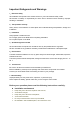
Welcome Thank you for purchasing our network video recorder! This user’s manual is designed to be a reference tool for your system. Please open the accessory bag to check the items one by one in accordance with the list below. Contact your local retailer ASAP if something is missing or damaged in the bag.
Important Safeguards and Warnings 1.Electrical safety All installation and operation here should conform to your local electrical safety codes. We assume no liability or responsibility for all the fires or electrical shock caused by improper handling or installation. 2.Transportation security Heavy stress, violent vibration or water splash are not allowed during transportation, storage and installation. 3.Installation Keep upwards. Handle with care.
z Accessories Check the accessories after opening the box: z Please refer to the packing list in the box * viii
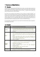
1 Features and Specifications 1.1 Overview This series NVR is a high performance network video recorder. This series product support local preview, multiple-window display, recorded file local storage, remote control and mouse shortcut menu operation, and remote management and control function. All these functions support this series product to be used in various situations. This series product supports centre storage, front-end storage and client-end storage.
• Support schedule record function. Save the recorded files in the HDD, client-end PC, or network storage server. You can search or playback the saved files at the local-end or via the Web. • Support network backup, USB record backup function, the recorded files can be saved in network storage server, peripheral USB device, burner and etc. Supervise NVR configuration and control power via Ethernet. Support management via WEB.
Window Split 4/8/9/16-window Multiple-chann el Playback Max 16-channel playback. Alarm Input 4/8/16-ch series product support 4/8/16-ch alarm input respectively. 3-ch alarm output Alarm Output Relay output. Relay (DC 30V 1A,AC 125V Including one controllable DC +12V output. Storage 2 built-in SATA ports. RS232 Port One RS232 port to debug transparent COM data. RS485 port One RS485 port to control PTZ. Support various protocols. USB Port 2 peripheral USB ports.
NVR6XXV Series System Resources Max support 16-ch standard definition with the transmission rate of 2mbps for each channel; 8-channel 720P, with the transmission rate of 4mbps for each channel; 4-channel 1080P, with the transmission rate of 8mbps for each channel; Support 20 online users at the same time, The image delay time of each channel is under 500ms. Operation System Embedded Linux real-time operation system Operation Interface WEB/Local GUI Video Compression H.
Power Button One power button in the rear panel. Power Button One power button in the front panel. IR Remote Control Receiver N/A Clock Built-in clock. Power Consumption <12W(Exclude HDD) Working Temperature 0℃~+50℃ Working Humidity 10℅-90℅ Air pressure 86kpa-106kpa Dimension 440mm*300mm*42.6mm Weight 1.5~2.5 KG(Exclude HDD) Installation Desk installation 1.3.
Window Split 4/8/9/16-window Multiple-chann el Playback Max 16-channel playback. Alarm Input 4/8/16-ch series product support 4/8/16-ch alarm input respectively. Alarm Output 6-ch alarm output Relay output. Relay (DC 30V 1A,AC 125V Including one controllable DC +12V output. 0.5A(Activation output)) 8 built-in SATA ports Storage 1 peripheral eSATA port RS232 Port One RS232 port to debug transparent COM data. RS485 port One RS485 port to control PTZ. Support various protocols.
2 Front Panel and Rear Panel 2.1 Front Panel 2.1.1 NVR7XXNS Series The front panel is shown as in Figure 2-1. Figure 2-1 Please refer to the following sheet for front panel button information. Name Icon Power button, press this button for three seconds to boot up or shut down DVR. Power button Shift Up/1 Down/4 Function In textbox, click this button to switch between numeral, English(Small/Capitalized),donation and etc. Shift Activate current control, modify setup, and then move up and down.
Backspace function: in numeral control or text control, press it for 1.5seconds to delete the previous character before the cursor In motion detection setup, working with Fn and direction keys to realize setup. In text mode, click it to switch between numeral, English character(small/capitalized) and etc. Realize other special functions. Fast play/7 _ Play previous/0 Reverse/Pau se/6 Various fast speeds and normal playback. In text mode, input number 7 (English character P/Q/R/S).
Figure 2-2 Please refer to the following sheet for front panel button information. Name Icon Power button Function Power button, press this button for three seconds to boot up or shut down NVR. z z z Assistant Fn z z z One-window monitor mode, click this button to display assistant function: PTZ control and image color. Backspace function: in numeral control or text control, press it for 1.5 seconds to delete the previous character before the cursor.
abnormal indication light IR Receiver 2.1.3 becomes red to alert you. It is to receive the signal from the remote control. IR NVR7XXN Series The front panel is shown as in Figure 2-3. Figure 2-3 Please refer to the following sheet for front panel button information. Name Icon Power button, press this button for three seconds to boot up or shut down DVR. Power button 0 In text mode, input number 0. It is the space button. 1,. In text mode, input number 1 and denotation.
Left Right Shift current activated control, W X When playback, click these buttons to control playback bar. Go to previous menu, or cancel current operation. ESC ESC When playback, click it to restore real-time monitor mode. Confirm current operation Enter ENTER Go to default button Go to menu Record REC Manually stop/start recording, working with direction keys or numeral keys to select the recording channel. Window switch Mult Click it to switch one-window/multiple-window.
Status indication light HDD abnormal i di ti Remote control indication light Status If there is Fn indication light, current status indication light is null. HDD HDD error occurs or HDD capacity is below specified threshold value, the light becomes red to alert you. ACT Remote control indication light Power Power indication light Record light 1-16 System is recording or not. It becomes on when system is recording.
Port Name Connection Function RS232 232 debug COM. It is for general COM debug to configure IP address or transfer transparent COM data. HDMI High Definition Media Interface High definition audio and video signal output port. It transmits uncompressed high definition video and multiple-channel data to the HDMI port of the display device. VGA VGA video output port VGA VGA video output port. Output analog video signal. It can connect to the monitor to view analog video. 1-16 Alarm input port.
Port Name Connection Function VIDEO OUT Video input port CVBS output MIC IN Audio input port Bidirectional talk input port. It is to receive the analog audio signal output from the devices such as mike phone, pickup. MIC OUT Audio output port Audio output port. It is to output the analog audio signal to the devices such as the sound box. 2.2.2 NVR6XXV Series The rear panel is shown as below. See Figure 2-5. Figure 2-5 Please refer to the following sheet for detailed information.
1-3 Port Name Connection Function Alarm input port 1-3. I/O port z z Alarm input port ground end NO Alarm output port Alarm input ground end. z C A RS485 port Alarm input port. When your alarm input device is using external power, please make sure the device and the NVS have the same ground. 3 groups of alarm output ports. (Group 1: port NO1~C1,Group 2:port NO2~ C2,Group 3:port NO3~C3)).Output alarm signal to the alarm device. Please make sure there is power to the external alarm device.
Figure 2-6 Please refer to the following sheet for detailed information. Port Name Connection Function Power button Power on/off button. Power input port Input AC 220V power. MIC IN Audio input port Bidirectional talk input port. It is to receive the analog audio signal output from the devices such as mike phone, pickup. MIC OUT Audio output port Audio output port. It is to output the analog audio signal to the devices such as the sound box. 1-16 Alarm input port 1-16.
Port Name Connection Function B RS485_B.It is the cable B. You can connect to the control devices such as speed dome PTZ. CTRL 12V Controller 12V power output. It is to control the on-off alarm relay output. It can be used to control the device alarm output. At the same time, it can also be used as the power input source of some devices such as the alarm detector. +12V +12V power output port. It can provide the power to some peripheral devices such as the camera or the alarm device.
Device Connection Please connect the speaker or the pickup to the first audio input port in the device rear panel. Then connect the earphone or the sound box to the audio output port in the PC. Login the Web and then enable the corresponding channel real-time monitor. Please refer to the following interface to enable bidirectional talk. Figure 2-7 Listening Operation At the device end, speak via the speaker or the pickup, and then you can get the audio from the earphone or sound box at the pc-end. 2.4.
In input box, you can select input methods. Left click the corresponding button on the panel you can input numeral/English character (small/capitalized). Here ← stands for backspace button. _ stands for space button. In English input mode: _stands for input a backspace icon and ← stands for deleting the previous character. In numeral input mode: previous numeral. _ stands for clear and ← stands for deleting the When input special sign, you can click corresponding numeral in the front panel to input.
3 HDD Installation For the first time install, please be aware that whether the HDDs have been installed. Strongly recommended to use the HDDs which we suggest you to use (high speed HDD that above 7200 rounds), we do not suggest you to use PC specified HDD. You can refer to the User’s Manual for recommended HDD brand. Please use HDD of 7200rpm or higher. Usually we do not recommend the PC HDD. Please follow the instructions below to install hard disk. All figures listed here for reference only. 3.
3.2 NVR6XXV Series ①Use 4 screws to secure the HDD ②Put the HDD to the HDD box at the front. ③Pull the HDD knob up when you put the HDD ④Put the knob back after you insert the HDD into the box in case the knob buckle may strike to the SATA board. the front panel. 3.3 NVR7XXN Series ① Use the screwdriver to loose the screws of the rear panel and then remove the front cover.
② Put the HDD to the HDD bracket in the chassis and then line up the four screws to the four holes in the HDD. Use the screwdriver to fix the screws firmly to secure HDD on the HDD bracket ③ Connect to the HDD data cable to the main board and the HDD port respectively. Loosen the power cable of the chassis and connect another end of the power cable to the HDD port. ④ After connect the cable, put the front cover back to the device and then fix screws of the rear panel.
4 Network Connection Please refer to Figure 4-1 for connection sample. The following figure is based on the NVR7XXN series product.
5 System Performance This series product max supports 16-channel standard definition video/high definition non-real-time video and the transmission rate is 1mbps per channel. It can also max supports 4-channel high definition video and the transmission rate is 8mbps. The delay time of each channel is below 500ms. Model System Performance 4-ch series Max support 4-channel video. Total resources:400/480fps@D1,200/240fps@720P.100/120@1080P. 8-ch series Max support 8-channel video.
6 GUI Operation Connect the device to the monitor and then connect a mouse and power cable. Click the power button at the rear panel and then boot up the device to view the analog video output. You can use the mouse to implement some GUI operation. 6.1 Login After device booted up, the system is in multiple-channel display mode. See Figure 6-1.Please note the displayed window amount may vary. The following figure is for reference only.
Preview Control The preview control function has the following features. z Support preview playback. In the preview desktop, system can playback previous 5-60 minutes record of current channel. Please go to the Main Menu->General to set real-time playback time. Support drag and play function. You can use your mouse to select any playback start time. Support playback, pause and exit function. Right now, system does not support slow playback and backward playback function.
channel is shown as an icon as 4 Remote device add shortcut 5 Bidirectional talk 6 . It is to go to the remote device connection interface. Support bidirectional talk function. Exit Playback control The playback control has the following features. z Support play, pause, and exit and drag function. z During the preview playback process, you can not see the channel title and record status of current channel. It will display the channel title and the record status once you exit the preview playback.
the cursor to highlight the icon, then double click mouse to enter the sub-menu. Figure 6-5 6.4 Search & Playback Click search button in the main menu, search interface is shown as below. See Figure 6-6. Usually there are three file types: z R: Regular recording file. z A: External alarm recording file. z M: Motion detection recording file.
Please refer to the following sheet for more information. SN 1 2 3 4 Name Function Display window zHere is to display the searched picture or file. zSupport 1/4/9/16-window playback. Search type Calendar zThe blue highlighted date means there is picture or file. Otherwise, there is no picture or file. zIn any play mode, click the date you want to see, you can see the corresponding record file trace in the time bar. Playback mode and channel selection pane. zPlayback mode:1/4/9/16.
W Backward play In normal play mode, left click the button, the file begins backward play. Click it again to pause current play. In backward play mode, click ►/ to restore normal play. │W/ X│ In playback mode, click it to play the next or the previous section. You can click continuously when you are watching the files from the same channel. In normal play mode, when you pause current play, you can click W│ and │X to begin frame by frame playback.
edit. You can see the corresponding slide bar in the time bar of the corresponding channel. You can adjust the slide bar or input the accurate time to set the file end time. Click this button again and then save current contents in a new file. . 12 Record type In any play mode, the time bar will change once you modify the search type. z 13 Smart search z z z z When system is playing, you can select a zone in the window to begin motion detect. Click the motion detect button to begin play.
6.5.1 HDD Information Here is to list hard disk type, total space, free space, and status. See Figure 6-8. ○ means current HDD is normal.. - means there is no HDD. If disk is damaged, system shows as “?”. Please remove the broken hard disk before you add a new one. Figure 6-8 In Figure 6-8, click view record d time button, HDD record time information interface is shown as in Figure 6-9. Figure 6-9 Parameter Function SATA 1-4 here means there are 4 HDDS.
Free space The HDD free capacity. Status HDD can work properly or not. Bad track Display there is bad track or not. Page up Click it to view previous page. Page down Click it to view the next page. View recording time Click it to view HDD record information (file start time and end time). View HDD type and capability Click it to view HDD property, status and etc, 6.5.2 BPS Here is for you to view current video data stream (KB/s) and occupied hard disk storage (MB/h). See Figure 6-10.
Figure 6-11 Click the Details button or double click the log item, you can view the detailed information. See Figure 6-12. Figure 6-12 6.5.4 Version Here is for you to view some version information. See Figure 6-13.
Figure 6-13 6.5.5 Online Users Here is for you manage online users connected to the local device. See Figure 6-14. You can disconnect one user or block one user if you have proper system right. Figure 6-14 6.5.6 Remote Device Information Here you can view the channel status of the remote device, connection log and network balance information and etc. Channel status: Here you can view the IPC status of the corresponding channel such as motion detect, video loss, camera masking, alarm and etc.
Figure 6-15 Connection log: In this interface, you can search the IPC log information of the corresponding channel. It includes IPC online, offline and etc. See Figure 6-16. Figure 6-16 Network Balance: Here you can view network data transmission speed, receive speed. See Figure 6-17. Figure 6-17 6.6 Setting In main menu, highlight setting icon and double click mouse. System setting interface is shown as below. See Figure 6-18.
Figure 6-18 Important Please note you need to have the proper right to implement the following operation. 6.6.1 General General setting includes the following items. See Figure 6-19. z System time: Here is for you to set system time z Date format: There are three types: YYYYY-MM-DD: MM-DD-YYYYY or DD-MM-YYYY. z Date separator: There are three denotations to separate date: dot, beeline and solidus. z DST: Here you can set DST time and date. Please enable DST function and then click set button.
z z Navigation bar: Check the box here, system displays the navigation bar on the interface. IPC Time Sync: You can input an interval here to synchronize the NVR time and IPC time. Note: Since system time is very important, do not modify time casually unless there is a must! Before your time modification, please stop record operation first! After completing all the setups please click save button, system goes back to the previous menu. Figure 6-19 Figure 6-20 Figure 6-21 6.6.
z z z z z z z z Type: Please select from the dropdown list. There are three options: regular/motion detect/alarm. You can set the various encode parameters for different record types. Compression: System supports H.264, MPEG4, MJPEG and etc. Resolution: The mainstream resolution type is IPC’s encoding config. Generally there is D1/720P/1080P. Frame rate: It ranges from 1f/s to 25f/s in NTSC mode and 1f/s to 30f/s in PAL mode. Bit rate type: System supports two types: CBR and VBR.
Figure 6-23 Figure 6-24 Figure 6-25 6.6.3 Schedule In the main menu, from setting to schedule, you can go to schedule menu. See Figure 6-26. z Channel: Please select the channel number first. You can select “all” if you want to set for the whole channels. z Week day: There are eight options: ranges from Saturday to Sunday and all. z Pre-record: System can pre-record the video before the event occurs into the file. The value ranges from 1 to 30 seconds depending on the bit stream.
z z z menu->Advanced->HDD Management). Please note this function is null if there is only one HDD. Snapshot: You can enable this function to snapshoot image when alarm occurs. Record types: There are four types: regular, motion detection (MD), Alarm, MD & alarm. Holiday setting: Click it you can see an interface shown as in Figure 6-27. Here you can set holiday date. Check the box, it means current channel shall record as your holiday setup.
as channel 1. Now you can select the channel you wan to paste such as channel 5/6/7. If you wan to save current setup of channel 1 to all channels, you can click the first box “ALL”. Click the OK button to save current copy setup. Click the OK button in the Encode interface, the copy function succeeded. Please note, if you select ALL in Figure 6-28, the record setup of all channels are the same and the Copy button becomes hidden. Figure 6-28 6.6.4 RS232 RS232 interface is shown as below.
Figure 6-29 6.6.5 Network Here is for you to input network information. See Figure 6-30. z IP Version: There are two options: IPv4 and IPv6. Right now, system supports these two IP address format and you can access via them. z MAC address: The host in the LAN can get a unique MAC address. It is for you to access in the LAN. It is read-only. z z z z z z z z IP address: Here you can use up/down button (ST) or input the corresponding number to input IP address.
Important For the IP address of IPv6 version, default gateway, preferred DNS and alternate DNS, the input value shall be 128-digit. It shall not be left in blank. After completing all the setups please click save button, system goes back to the previous menu. Figure 6-30 6.6.5.1 Network Seting Network setting interface is shown as in Figure 6-31. Please draw a circle to enable corresponding function and then double click current item to go to setup interface. Figure 6-31 6.6.5.
Figure 6-32 6.6.5.3 NTP Setup You need to install SNTP server (Such as Absolute Time Server) in your PC first. In Windows XP OS, you can use command “net start w32time” to boot up NTP service. NTP setup interface is shown as in Figure 6-33. z Host IP: Input your PC address. z Port: This series NVR supports TCP transmission only. Port default value is 123. z Update interval: minimum value is 1. Max value is 65535. (Unit: minute) z Time zone: select your corresponding time zone here.
Figure 6-33 6.6.5.4 Multiple Cast Setup Multiple-cast setup interface is shown as in Figure 6-34. Figure 6-34 Here you can set a multiple cast group. Please refer to the following sheet for detailed information. z IP multiple cast group address -224.0.0.0-239.255.255.255 -“D” address space z The higher four-bit of the first byte=”1110” z Reserved local multiple cast group address -224.0.0.0-224.0.0.255 -TTL=1 When sending out telegraph -For example 224.0.0.1 All systems in the sub-net 224.0.0.
Multiple cast PORT: 3666. After you logged in the Web, the Web can automatically get multiple cast address and add it to the multiple cast groups. You can enable real-time monitor function to view the view. Please note multiple cast function applies to special series only. 6.6.5.5 PPPoE PPPoE interface is shown as in Figure 6-35. Input “PPPoE name” and “PPPoE password” you get from your ISP (Internet service provider). Click save button, you need to restart to activate your configuration.
Figure 6-36 Please note NNDS type includes: CN99 DDNS, NO-IP DDNS, Private DDNS, and Dyndns DDNS. All the DDNS can be valid at the same time, you can select as you requirement. Private DDNS function shall work with special DDNS server and special Professional Surveillance Software (PSS). Private DDNS and Client-end Introduction 1) Background Introduction Device IP is not fixed if you use ADSL to login the network. The DDNS function allows you to access the NVR via the registered domain name.
z z Do not register frequently. The interval between two registrations shall be more than 60 seconds. Too many registration requests may result in server attack. System may take back the domain name that is idle for one year. You can get a notification email before the cancel operation if your email address setup is OK. 6.6.5.7 UPNP The UPNP protocol is to establish a mapping relationship between the LAN and the WAN. Please input the router IP address in the LAN in Figure 6-30.
Figure 6-37 Figure 6-38 6.6.5.8 WIFI Setting You can view the WIFI connection status in the Network Setting interface. See Figure 6-39. You can view current connection status and IP address if there is a connection. Figure 6-39 The WIFI interface is shown as below. See Figure 6-40.
z z z z Auto connect WIFI: Check the box here, system automatically connects to the previous WIFI hotspot. Refresh: You can click it to search the hotspot list again. It can automatically add the information such as the password if you have set it before. Disconnect: Here you can click it to turn off the connection. Connect: Here you can click it to connect to the hotspot. System needs to turn off current connection and then connect to a new hotspot if there is connection of you selected one.
Figure 6-42 z WIFI working status: Here you can view current connection status. Please note: z After successful connection, you can see WIFI connection icon at the top right corner of the preview interface. z When the hotspot verification type is WEP, system displays as AUTO since the device can not detect its encryption type. z System does not support verification type WPA and WPA2. The display may become abnormal for the verification type and encryption type.
Title: Please input email subject here. System support English character and Arabic number. Max 32-digit. z Receiver: Please input receiver email address here. System max supports 3 email boxes. z SSL enable: System supports SSL encryption box. z Interval: The send interval ranges from 0 to 3600 seconds. 0 means there is no interval. z Health email enable: Please check the box here to enable this function. This function allows the system to send out the test email to check the connection is OK or not.
Figure 6-46 You can use a PC or FTP login tool to test setup is right or not. For example, you can login user ZHY to FTP://10.10.7.7 and then test it can modify or delete folder or not. See Figure 6-47. H140TU UTH Figure 6-47 System also supports upload multiple NVRs to one FTP server. You can create multiple folders under this FTP. In Figure 6-30, select FTP and then double click mouse. You can see the following interface. See Figure 6-48.
Figure 6-48 Figure 6-49 6.6.5.11 Alarm center Interface is pre-reserved for the users to develop this function. 6.6.5.12 SNMP SNMP is an abbreviation of Simple Network Management Protocol. It provides the basic network management frame of the network management system. The SNMP widely used in many environments. It is used in many network device, software and system. You can set in the following interface. See Figure 6-50.
Figure 6-50 Please enable the SNMP function. Use the corresponding software tool (MIB Builder and MG-SOFT MIB Browser. You still need two MIB file: BASE-SNMP-MIB, NVR-SNMP-MIB) to connect to the device. You can get the device corresponding configuration information after successfully connection. Please follow the steps listed below to configure. z In Figure 6-50, check the box to enable the SNMP function. Input the IP address of the PC than is running the software in the Trap address.
Figure 6-51 2) The proxy server software developed from the SDK. Please open the software and input the global setup. Please make sure the auto connection port here is the same as the port you set in the previous step. 3) Now you can add device. Please do not input default port number such as the TCP port in the mapping port number. The device ID here shall be the same with the ID you input in Figure 6-51. Click Add button to complete the setup. 4) Now you can boot up the proxy server.
z z z z z z z z PTZ activation: When an alarm occurred, system can activate the PTZ operation. The PTZ activation lasts an anti-dither period. In the Pan/Tilt/Zoom interface (Main menu->Setting-> Pan/Tilt/Zoom), please set video channel, speed dome protocol and etc. Select the channel of current speed dome as current monitor video and the right click mouse to select Pan/Tilt/Zoom item. Now you can set preset, tour pattern.
Finally, you can set the alarm input as the local alarm and then select the record channel. The select channel begins alarm record when an alarm occurred. Please note system begins the alarm record instead of the MD record if the local alarm and MD event occurred at the same time. Tour: Here you can enable tour function when alarm occurs. System supports 1/8-window tour. Please go to chapter 6.6.9 Display for tour interval setup.
Figure 6-54 Figure 6-55 6.6.7 Detect Go to Detect Menu In the main menu, from Setting to Detect, you can see motion detect interface. See Figure 6-56.There is three detection types: motion detection, video loss, camera masking. Motion Detect Detection menu is shown as below. See Figure 6-56 z Event type: from the dropdown list you can select motion detection type. z Channel: select the channel to activate recording function once alarm occurred.
z z z Alarm upload: System can upload the alarm signal to the network (including alarm centre) if you enabled current function. Send email: System can send out email to alert you when alarm occurs. PTZ activation: Here you can set PTZ movement when alarm occurs. Such as go to preset, tour &pattern when there is an alarm. Click “select” button, you can see an interface is shown as in Figure 6-58. Period: Click set button, you can see an interface is shown as in Figure 6-59.
Figure 6-57 Figure 6-58 Figure 6-59 Figure 6-60 Video Loss In Figure 6-56, select video loss from the type list.
Figure 6-61.This function allows you to be informed when video loss phenomenon occurred. You can enable alarm output channel and then enable show message function. Tips: You can enable preset activation operation when video loss occurs. Figure 6-61 Camera Masking When someone viciously masks the lens, or the output video is in one-color due to the environments light change, the system can alert you to guarantee video continuity. Camera masking interface is shown as in Figure 6-62.
6.6.8 PTZ Note: All the operations here are based on PELCOD protocol. For other protocols, there might be a little difference. Cable Connection Please follow the procedures below to go on cable connection z Connect the dome RS485 port to NVR 485 port. z Connect dome video output cable to NVR video input port. z Connect power adapter to the dome. PTZ Setup Note: The camera video should be in the current screen.
z Step: value ranges fro 1 to 8. z Zoom z Focus z Iris Please click icon and to adjust zoom, focus and iris. Figure 6-64 In Figure 6-64, please click direction arrows to adjust PTZ position. There are total 8 direction arrows. Figure 6-65 Here is a sheet for you reference. Name Function key function Zoom Wide Focus Near Iris Close 6.6.9 Shortcut key Function key function Far Shortcut Key │_ Far ►│ W Open f Display Display setup interface is shown as below. See Figure 6-66.
Please highlight icon to select the corresponding function. After completing all the setups please click save button, system goes back to the previous menu. Figure 6-66 In Figure 6-66, click modify button after channel. You can see an interface shown as in Figure 6-67. Please note all your modification here applies to local end only. You need to refresh web or client-end to get the latest channel name. System max support 25-digital character.
6.6.10 Default Click default icon, system pops up a dialogue box. You can highlight to restore default factory setup. z Select all z General z Encode z Schedule z RS232 z Network z Alarm z Detect z Pan/tilt/zoom z Display z Channel name Please highlight icon to select the corresponding function. After all the setups please click OK button, system goes back to the previous menu.
Figure 6-69 6.6.11.2 Built-in Switch Setup From Network->Network Server->Switch, you can set switch IP address, subnet mask, gateway and etc. See Figure 6-70. Figure 6-70 6.6.11.3 Remote Device In the main menu, click the Remote Device icon to go to the corresponding interface. See Figure 6-71.
Figure 6-71 The remote device interface is shown as in Figure 6-72. z IP search: Click it to search IP address. z Add: Click it to connect to the selected device and add it to the Added device list. Support Batch add. z Show filter: You can use it to display the specified devices from the added device. z Delete: Please select one device in the Added device list and then click it to remove. z Manual add: Click it to add the IPC manually. The port number is 37777.
Model System Performance 4-ch series Max support 4-channel video. Total resources:400/480fps@D1,200/240fps@720P.100/120@1080P. 8-ch series Max support 8-channel video. Total resources:400/480fps@D1,200/240fps@720P.100/120@1080P. 16-ch series Max support 16-channel video. Total resources:400/480fps@D1,200/240fps@720P.100/120@1080P. This series product supports the IPC from many popular manufactures such as Sony, Hitachi, Axis, Samsung, and Dahua. Figure 6-73 6.6.11.
Figure 6-74 Figure 6-75 6.7 Advanced Double click advanced icon in the main window, the interface is shown as below. See Figure 6-76.There2 are total eight function keys: HDD management, alarm output, abnormity, manual record, account, auto maintenance, TV adjust and video matrix. Figure 6-76 6.7.1 HDD Management Here is for you to view and implement hard disk management. See Figure 6-77. You can see current HDD type, status, capacity and record time.
Figure 6-77 Figure 6-78 For the HDD group setup operation, please note: z Each channel’s records can be stored into the specified HDD Group. z Each HDD Group is corresponding to several hard disks, while one hard disk is only included in one HDD Group. z Each channel is only corresponding with one HDD Group, while one HDD Group can store records from several channels. z HDD Group is only available for read-write HDD and self-defined disks, other types of hard disks cannot be set as HDD Group.
The number of hard disk from 1 to 12 is shown in the “HDD No.” column. If there is a mark in the front of the number, it means this interface have access to the hard disk, otherwise it does not have access to the hard disk. The “HDD Group” column lists the HDD Group number of current hard disk. When you are setting the HDD Group, please check the box of the hard disk, and then choose the corresponding HDD Group number and save the settings.
Figure 6-80 Channels Setting Click the button named with “Channels Settings” at the top right corner of the Figure 6-77, system will pop up an interface shown as in Figure 6-81. When you are setting the configurations of the channels setting, please select relevant channels first (such as channel 1 to 16), and then select the HDD Group NO. Please click the Save button to save current setup.
Figure 6-82 6.7.2 Abnormity Abnormity interface is shown as in Figure 6-83. z Event type: There are several options for you such as disk error, no disk, disconnection, IP conflict and etc. z Alarm output: Please select alarm activation output port (multiple choices). z Latch: Here you can set corresponding delaying time. The value ranges from 10s-300s. System automatically delays specified seconds in turning off alarm and activated output after external alarm cancelled.
Figure 6-84 6.7.4 Manual Record Note: You need to have proper rights to implement the following operations. Please make sure the HDD has been properly installed. 6.7.4.1 Manual record menu There are two ways for you to go to manual record menu. z Right click mouse or in the main menu, Advanced->Manual Record. z In live viewing mode, click record button in the front panel or record button in the remote control. Manual record menu is shown as in Figure 6-85. 6.7.4.
Figure 6-86 6.7.4.4 Enable all channel recording Highlight ○ below All, you can enable all channel recording. z All channel schedule record Please highlight “ALL” after “Schedule”. See Figure 6-87. When system is in schedule recording, all channels will record as you have previously set (Main menu->Setting->Schedule). The corresponding indication light in front panel will turn on. Figure 6-87 z All channel manual record Please highlight “ALL” after “Manual.” See Figure 6-88.
Figure 6-89 6.7.5 Account Here is for you to implement account management. See Figure 6-90. Here you can: z Add new user z Modify user z Add group z Modify group z Modify password. For account management please note: z For the user account name and the user group, the string max length is 6-byte. The backspace in front of or at the back of the string is invalid. There can be backspace in the middle. The string includes the valid character, letter, number, underline, subtraction sign, and dot.
Figure 6-90 6.7.5.1 Modify Password Click password button, the interface is shown as in Figure 6-91. Here you can modify account password. Please select the account from the dropdown list, input the old password and then input the new password twice. Click the Save button to confirm current modification. For the users of user account right, it can modify password of other users. Figure 6-91 6.7.5.2 Add/Modify Group Click add group button, the interface is shown as below. See Figure 6-92.
Figure 6-92 6.7.5.3 Add/Modify User Click add user button, the interface is shown as in Figure 6-93. Please input the user name, password, select the group it belongs to from the dropdown list. Then you can check the corresponding rights for current user. For convenient user management, usually we recommend the general user right is lower than the admin account. The modify user interface is similar to Figure 6-93. Figure 6-93 6.7.
Figure 6-94 6.7.7 Config Backup The configuration file backup interface is shown as below. See Figure 6-95. This function allows you to copy current system configuration to other devices. Figure 6-95 6.8 Shutdown Double click shutdown button, system pops up a dialogue box for you to select. See Figure 6-96. z Logout menu user: log out menu. You need to input password when you login the next time. z Restart application: reboot device. z Shutdown: system shuts down and turns off power.
Figure 6-96 82
7 Quick Configuration Tool 7.1 Overview Quick configuration tool can search current IP address, modify IP address. At the same time, you can use it to upgrade the device. Please note the tool only applies to the IP addresses in the same segment. 7.2 Operation Double click the “ConfigTools.exe” icon, you can see an interface is shown as in Figure 7-1. In the device list interface, you can view device IP address, port number, subnet mask, default gateway, MAC address and etc.
Select the “Open Device Web” item; you can go to the corresponding web login interface. See Figure 7-3. Figure 7-3 If you want to modify the device IP address without logging in the device web interface, you can go to the configuration tool main interface to set. In the configuration tool search interface (Figure 7-1), please select a device IP address and then double click it to open the login interface. Or you can select an IP address and then click the Login button to go to the login interface.
Figure 7-5 85
8 Web Operation 8.1 General Introduction The device web provides channel monitor menu tree, search, alarm setup, system setup, PTZ control and monitor window. Important The following operation is based on 16-channel series device. 8.1.1 Preparation Before log in, please make sure: z Network connection is right z NVR and PC network setup is right. Please refer to network setup(main menu->setting->network) z Use order ping ***.***.***.***(* NVR IP address) to check connection is OK or not.
System pops up warning information to ask you whether install webrec.cab control or not. Please click yes button. If you can’t download the ActiveX file, please modify your settings as follows. See Figure 8-2. Figure 8-2 IE Safety Setup After installation, the interface is shown as below. See Figure 8-3. Figure 8-3 Login interface Please input your user name and password. Default factory name is admin and password is admin.
Note: For security reasons, please modify your password after you first login. 8.2 LAN Mode ② For the LAN mode, after you logged in, you can see the main window. See Figure 8-4. ③ ④ ① ⑤ ⑥ Figure 8-4 Main Interface There are six sections: z Section 1: Monitor channel menu tree z Section 2: System menu z Section 3: PTZ control z Section 4: Video setup and other setup z Section 5: Preview window z Section 6: Monitor window switch 8.2.
Figure 8-5 Monitor Channel Menu Tree Please refer to the following sheet for detailed information. Parameter Function CAM 1 to CAM 16 channel 1 to channel 16 Open all /close all Click this button to open all video channels. Once all video channels are open, it becomes close all button. Start Dialogue You can click this button to enable audio talk. Click 【▼】 to select bidirectional talk mode. There are four options: DEFAULT, G711a,G711u and PCM.
Local play The Web can playback the saved (Extension name is dav) files in the PC-end. Click local play button, system pops up the following interface for you to select local play file. See Figure 8-6. Figure 8-6 Refresh Click this button to refresh monitor channel name. Please left click one monitor to view real-time video, the monitor window is shown as in Figure 8-7. Figure 8-7 Real-time Monitor Please refer to the following sheet for monitor window parameter information.
8.2.2 Change show mode Resize or switch to full screen mode. Local record When you click local record button, the system begins recording. The recorded file is saved to system folder: \ RecordDownload(default). Snapshot You can snapshoot important video. All images are memorized in system folder: \ picture download (default). Audio Turn on or off audio. Close video Close video in current window. System Menu System menu is shown as in Figure 8-8. Please refer to chapter 8.
You can click this icon to display or hide the PTZ control platform. Figure 8-10 PTZ Interface Click PTZ set button, the interface is shown as in Figure 8-11.
Please refer to the following sheet for PTZ setup information. Parameter Function Scan z z Move the camera to you desired location and then click left limit button. Then move the camera again and then click right limit button to set a right limit. Preset Use direction keys to move the camera to your desired location and then input preset value. Click add button, you have set one preset. Tour z z z Input auto tour value and preset value. Click add button, you have added one preset in the tour.
It is to adjust monitor video contrast ness. All the operation here applies to WEB end only. It is to adjust monitor video saturation. It is to adjust monitor video hue. Reset Restore system default value. Click more button, the interface is shown as in Figure 8-13. Figure 8-13 Color and More Please refer to the following sheet for detailed information. Parameter Function More Picture Path Click picture path button, system pops up an interface for you to modify path.
Figure 8-14 Please refer to the following contents for LAN and WAN login difference. 1) In the WAN mode, system opens the main stream of the first channel to monitor by default. The open/close button on the left pane is null. 2) You can select different channel and different monitor mode at the bottom of the interface. See Figure 8-15. Figure 8-15 Important The window display mode and the channel number are by default. For example, for the 16-channel, the max window split mode is 16.
main stream. A stands for 4) When you switch from Monitor to Search or Configuration, system pops a dialogue box asking you leave current interface or not. See Figure 8-16.Click the OK button, system will close current monitor window. For example, you click the Config button when you are monitoring, system pos up a following dialogue. Click the OK button, system closes current monitor interface and open the configuration interface.
Figure 8-17 Version Information 8.4.1.2 HDD information Here you can view local storage status such as free capacity and total capacity. See Figure 8-18. Figure 8-18 HDD Information 8.4.1.3 Log Here you can view system log.
Figure 8-19 Log Please refer to the following sheet for log parameter information. Parameter Function Type Log types include: system operation, configuration operation, data management, alarm event, record operation, user management, log clear and file operation. Start time Set time to start search. Finish time Set time to finish search Search You can select log type from the drop down list and then click search button to view the list.
Figure 8-20 General Setup Figure 8-21 DST Figure 8-22 DST Please refer to the following sheet for detailed information. Parameter Function System Time Here is for you to modify system time. Please click Save button after your completed modification Sync PC You can click this button to save the system time as your PC current time. Data Format Here you can select data format from the dropdown list.
Data Separator Please select separator such as – or /. Time Format There are two options: 24-H and 12-H. DST Here you can set day night save time begin time and end time. See Figure 8-21and Figure 8-22. Language Here you can view the system current language. You can select from the dropdown list. HDD Full There are two options: stop recording or overwrite the previous files when HDD is full. Pack Duration Here you can select file size. The value ranges from 1 to 120 (minute).
Audio / video For the main stream, recorded file only contains video by default. You need to draw a circle here to enable audio function. For extra stream, you need to draw a circle to select the video first and then select the audio if necessary. Main code stream types are D1/HD1/2CIF/CIF/QCIF Resolution Channel 1~16 extra code stream supports CIF/QCIF. Frame rate PAL: 1f/s-25f/s;NTSC: 1f/s-30f/s There are two options: VBR and CBR. Bit rate Please note, you can set video quality in VBR mode only.
Figure 8-25 Schedule Time Figure 8-26 Copy Figure 8-27 Please refer to the following sheet for detailed information. Parameter Function Channel Please select a channel first.
Parameter Function Pre-record Please input pre-record value here. When alarm record or motion detection record occurs, system can record the several seconds video before activating the record operation into the file. (Depends on data size). Setup In Figure 8-24, click set button, you can go to the corresponding setup interface. See Figure 8-25. Please set schedule period and then select corresponding record type: schedule, motion detection, and alarm.
Parameter Function RS232 There is only one option COM 01, corresponding to RS232. Function Console is for debug. Control keyboard: Switch between RS232 and control keyboard. Network keyboard: COM control protocol. You can use network keyboard to control NVR via COM. Transparent COM: Network user can communicate with RS232 COM device. PTZ matrix: PTZ matrix protocol. You can use the device to control the PTZ matrix. Data Bit The value ranges from 5 to 8. Stop Bit There are three options: 1/2.
Parameter Function MAC Address The host in the LAN can get a unique MAC address. It is for you to access in the LAN. It is read-only. IP Address Here you can use up/down button (ST) or input the corresponding number to input IP address. Then you can set the corresponding subnet mask the default gateway. Subnet Prefix The input value ranges from 0 to 128. It is to mark a specifi network MAC address. Usually it includes an organization multiple-level.
Parameter Remote host Function PPPOE Input the user name and password which ISP(Internet service supplier) provided and chose enable. Reboot system after configuration is saved and the device will auto connect to Internet. The IP address is the WAN IP. There are two conditions for reboot, 1. The user must have the authority to reboot device. 2. There is no user login the system menu on the local end After PPPOE dial succeed, get the current IP address and visit this IP address via WEB.
Parameter Function Subject Input email subject here. Max 32-digit. Address Input receiver email address here. Max input three addresses. Interval Please input the send interval value here. DDNS The DDNS interface is shown as in Figure 8-32. Figure 8-32 DDNS Please refer to the following sheet for detailed information. Parameter Function Server Type You can select DDNS protocol from the dropdown list and then enable DDNS function.
access the NVR via the registered domain name. Besides the general DDNS ,the private DDNS works with the device from the manufacturer so that it can add the extension function. 2) Function Introduction The private DDNS client has the same function as other DDNS client end. It realizes the bonding of the domain name and the IP address. Right now, current DDNS server is for our own devices only. You need to refresh the bonding relationship of the domain and the IP regularly.
Figure 8-34 NAS Setup Please refer to the following sheet for detailed information. Parameter Function NAS enable Please select network storage protocol and then enable NAS function. The network storage protocol includes FTP. Server IP Input remote storage server IP address. Port Input Remote storage server port number. User Name Log in user account. File length The max files length when you transfer the file. When the input value is 0, then system upload the whole files.
Here you can realize network time synchronization. Please enable current function and then input server IP, port number, time zone and time. Figure 8-35 NTP Please refer to the following sheet for detailed information. Parameter Function Enable Enable NTP function or not. Server IP Server IP address Port Server port. System supports TCP only and default port value is 123. Time Zone Device current time zone. Update Interval Time update interval value.
Figure 8-36 Alarm Centre UNPN Go to the UPnP interface, you can see an image is shown as in Figure 8-37. It allows you to establish the mapping relationship between the LAN and the public network. Here you can also add, modify or remove UPNP item. Figure 8-37 UNPN SNMP The SNMP interface is shown as in Figure 8-38. SNMP is an abbreviation of Simple Network Management Protocol. It provides the basic network management frame of the network management system. The SNMP widely used in many environments.
Please refer to chapter 6.6.5.12 SNMP for detailed information. Figure 8-38 SNMP 8.4.2.6 Alarm Alarm setup interface is shown as in Figure 8-39.
Figure 8-40 PTZ Setup Figure 8-41 Please refer to the following sheet for detailed information. Parameter Function Event Type Event type: There are four types. Local input/network input/IPC external/IPC offline alarm. Local input alarm: The alarm signal system detects from the alarm input port. Network input alarm: It is the alarm signal from the network. IPC external alarm: It is the on-off alarm signal from the front-end device and can activate the local NVR.
Parameter Function Type There are two options: normal open and normal close. NO becomes activated in low voltage, NC becomes activated in high voltage. Period Alarm record function becomes activated in the specified periods. There are six periods in one day. Please draw a circle to enable corresponding period. Select date. If you do not select, current setup applies to today only. You can select all week column to apply to the whole week.
signal which meets the senility standard that is previously set. See Figure 8-42.
Figure 8-42 Detect Please refer to the following sheet for detailed information. Parameter Function Event type Motion detect, video loss and video masking Channel select the channel to activate recording function Sensitivity System supports 6 levels. The sixth level has the highest sensitivity. Enable button Tick to enable There are PAL22X18/NTSC22X15 small zones. Region Blue area is the detection zone. Right click to view in full screen, click OK before exit to save the setup.
and speed dome connection is OK. Figure 8-43 PTZ Please refer to the following sheet for detailed information. Parameter Function Channel You can select monitor channel from the dropdown list. . Protocol Select the corresponding dome protocol.(such as PELCOD) Address Set corresponding dome address. Default value is 1. Please note your setup here shall comply with your dome address; otherwise you can not control the speed dome. Baud Rate Select the dome baud rate. Default setup is 115200.
Figure 8-44 Default and Backup Please refer to the following sheet for detailed information. Parameter Function Select All Restore factory default setup. Export Configuration Export system configuration to local PC. Import Configuration Import configuration from PC to the system. 8.4.3 Advanced 8.4.3.1 HDD Management Please select the storage device first and then you can see the items on your right become valid. You can check the corresponding item here. See Figure 8-45.
Please refer to the following sheet for detailed information. Parameter Function Format Clear data in the HDD. Read/write Set current HDD as read/write Read only Set current HDD as read. Redundant Set current HDD as redundant HHD. Recover Fix the HDD error. Right now the device does not support this function. 8.4.3.2 Abnormity The interface is shown as in below. See Figure 8-46 and Figure 8-47.
Parameter Function Event Type The abnormal events include: no disk, no space, disk error, offline, IP conflict. You need to draw a circle to enable this function. Threshold: It refers to the HDD free space threshold. Normal Out The corresponding alarm output channel when alarm occurs. Latch The alarm output can delay for the specified time after alarm stops. The value ranges from 10s to 300s.
Please refer to the following sheet for detailed information. Parameter Function Alarm output The alarm output channel may vary. The interface here is for reference only. Please click the corresponding number and then click the trigger button. Trigger Enable/disable alarm output. Please note once you activate an alarm manually, you need to click the output channel number again and then click trigger button to disable it. Otherwise the alarm can not be cancelled. Refresh Search alarm output status.
Figure 8-50 Account Figure 8-51 Add user Please refer to the following sheet for detailed information. Parameter Function User Input the user name of the new established account. Reusable The reusable account means that this account can be used in more than one PC at the same time.
Password Input the password of the new established account. Confirm Input the password of the new established account again. Group Select the group which the new account belongs to. Memo Memo about the new account Authority/All User can select all to entitle this account to all authorities or set authority of each item respectively. 8.4.3.6 Snapshot Snapshot interface is shown as in Figure 8-52. Here you can set snap mode, frequency, resolution and quality of each channel. Figure 8-52 8.4.3.
Figure 8-53 Auto Maintenance 8.4.3.8 Remote device Remote device interface is shown as in Figure 8-54.
Figure 8-55 Manual Add Please refer to the following sheet for detailed information. Parameter Function Remote device information Here you can see searched remote device name, IP address, TCP port and manufacturer name. Channel Please select the local device channel number to connect to the remote device. You need to highlight the enable item to activate this function. Now you can see remote device type, IP address and etc.
Figure 8-56 Preview Control 8.4.4 Additional Function 8.4.4.1 Auto register The auto register interface is shown as in Figure 8-57. You can set the server IP and port if you want to use the auto register function. After the device registered to the server, you can access the device after the client-end connected to the server. Figure 8-57 Auto register 8.4.4.2 Mobile Config The mobile setup interface is shown as in Figure 8-58.
Figure 8-58 Mobile Setup 8.4.4.3 WIFI Config The WIFI interface is shown as in Figure 8-59. Here you can view WIFI connection status. System displays as no connection if there is no connection. You can view connection status and IP address if there is a connection. See Figure 8-60.
Figure 8-60 Please refer to the following sheet for detailed information. Parameter Function Refresh Search hotspot again and system can automatically add the information such as password (If there is any record of the hotspot.) WIFI working information Here you can view current connection status. You can view connection status and IP address if there is a connection. Otherwise system shown as there is no hotspot connection. 8.
Figure 8-61 Then please click search button, you can see the corresponding files in the list. See Figure 7-61. Figure 8-62 Select the file(s) you want to download and then click download button, system pops up a dialogue box shown as in Figure 7-62, then you can specify file name and path to download the file(s) to your local pc.
Figure 8-63 Load more It is for you to search record or picture. You can select record channel, record type and record time to download. See Figure 8-64. Figure 8-64 In Figure 8-64, there is a remote back pane at the left bottom of the pane. It allows you to backup the record or picture to your local USB storage media via the Web remotely. Click the search button; you can view the available storage device. See Figure 8-64. Please select from the dropdown list and then begin the backup.
Figure 8-65 Now you can see system begins download and the download button becomes stop button. You can click it to terminate current operation. At the bottom of the interface, there is a process bar for your reference. 8.6 Alarm Click alarm function, you can see an interface is shown as in Figure 8-66. Here you can set device alarm type and alarm sound setup. When alarm occurs, system can display the alarm information in the corresponding interface.
Figure 8-66 Alarm Please refer to the following sheet for detailed information. Type Parameter Function Alarm Type Video loss System alarms when video loss occurs. Motion detection System alarms when motion detection alarm occurs, Disk full System alarms when disk is full. Disk error System alarms when disk error occurs. Camera masking System alarms when camera is viciously masking. External alarm Alarm input device sends out an alarm. Offline alarm NVR local-end offline alarm.
Type Parameter Function Sound pop up System sends out alarm sound when alarm occurs. You can specify as you wish. Path Here you can specify alarm sound file. 8.7 About Click about button, you can view the web information. See Figure 8-67. Figure 8-67 About 8.8 Log out Click log out button, you can go back to log in interface. See Figure 8-68.
9 FAQ 1. Device can not boot up properly. There are following possibilities: z Input power is not correct. z Power connection is not correct. z Power switch button is damaged. z Program upgrade is wrong. z HDD malfunction or something wrong with HDD ribbon. z Seagate DB35.1,DB35.2,SV35 or Maxtor 17-g has compatibility problem. Please upgrade to the latest version to solve this problem. z Front panel error. z Main board is damaged. 2. Device often automatically shuts down or stops running.
z Device color or brightness setup is not correct. 6. Can not search local records. There are following possibilities: z HDD ribbon is damaged. z HDD is broken. z Upgraded program is not compatible. z The recorded file has been overwritten. z Record function has been disabled. 7. Video is distorted when searching local records. There are following possibilities: z Video quality setup is too low. z Program read error, bit data is too small. There is mosaic in the full screen.
z PTZ decoder and device address is not compatible. z When there are several decoders, please add 120 Ohm between the PTZ decoder A/B cables furthest end to delete the reverberation or impedance matching. Otherwise the PTZ control is not stable. z The distance is too far. 12. Motion detection function does not work. There are following possibilities: z Period setup is not correct. z Motion detection zone setup is not correct. z Sensitivity is too low.
z System uses too much CPU resources. Please stop record first and then begin backup. z Data amount exceeds backup device capacity. It may result in burner error. z Backup device is not compatible. z Backup device is damaged. 17. Keyboard can not control device. There are following possibilities: z Device serial port setup is not correct z Address is not correct z When there are several switchers, power supply is not enough. z Transmission distance is too far. 18.
z There is no DivX503Bundle.exe control when you play the file transformed to AVI via media player. z No DivX503Bundle.exe or ffdshow-2004 1012 .exe in Windows XP OS. 23. I forgot local menu operation password or network password Please contact your local service engineer or our sales engineer for help. We can guide you to solve this problem. 24. There is no video. The screen is in black. There are following possibilities: z IPC IP address is not right. z IPC port number is not right.
10 Appendix A HDD Capacity Calculation Calculate total capacity needed by each device according to video recording (video recording type and video file storage time). Step 1: According to Formula (1) to calculate storage capacity qi that is the capacity of each channel needed for each hour, unit Mbyte.
11 Appendix B Compatible SATA HDD brand Series Capacity Sandisk Cruzer Micro 512M Sandisk Cruzer Micro 1G Sandisk Cruzer Micro 2G Sandisk Cruzer Freedom 256M Sandisk Cruzer Freedom 512M Sandisk Cruzer Fredom 1G Sandisk Cruzer Freedom 2G Kingston Data Traveler II 1G Kingston Data Traveler II 2G Kingston Data Traveler 1G Kingston Data Traveler 2G Maxell USB Flash Stick 128M Maxell USB Flash Stick 256M Maxell USB Flash Stick 512M Maxell USB Flash Stick 1G Maxell
Teclast Ti Cool 2G 141
12 Appendix C Compatible USB List Manufacturer Model Capacity Sandisk Cruzer Micro 512M Sandisk Cruzer Micro 1G Sandisk Cruzer Micro 2G Sandisk Cruzer Freedom 256M Sandisk Cruzer Freedom 512M Sandisk Cruzer Fredom 1G Sandisk Cruzer Freedom 2G Kingston Data Traveler II 1G Kingston Data Traveler II 2G Kingston Data Traveler 1G Kingston Data Traveler 2G Maxell USB Flash Stick 128M Maxell USB Flash Stick 256M Maxell USB Flash Stick 512M Maxell USB Flash Stick 1G
Teclast Ti Cool 512M Teclast Ti Cool 1G Teclast Ti Cool 2G 143
13 Appendix D Compatible Displayer List Brand Model Dimension (Unit: inch) BENQ(LCD) ET-0007-TA 19-inch (wide screen) DELL(LCD) E178FPc 17-inch BENQ(LCD) Q7T4 17-inch BENQ(LCD) Q7T3 17-inch LENOVO(LCD) LXB-L17C 17-inch SANGSUNG(LCD) 225BW 22-inch (wide screen) LENOVO(CRT) LXB-FD17069HB 17-inch LENOVO(CRT) LXB-HF769A 17-inch LENOVO(CRT) LX-GJ556D 17-inch Samsung (LCD) 2494HS 24-inch Samsung (LCD) P2350 23-inch Samsung (LCD) P2250 22-inch Samsung (LCD) P2370G 23-inch
14 Appendix E No-IP DDNS Please double click DDNS to go to the configuration interface. You can see an interface is shown as in Figure 14-1. Figure 14-1 y DDNS Type: You can select from the dropdown list. There are five options: No-IP, DynDNS, CN99, Private and Oray. y Server IP: You can use ping command to get server’s IP y Port: input server port here. y Domain Name: Get the domain name you get from your DDNS service provider. y User: Get the user name you get from your DDNS service provider.
device’s connection IP, and modify its IP on the table of data from the server. Then we have a constant domain name in the Web browser, along with the HTTP port, send a request to identify the car IP of the domain name typed. The server will direct the domain name to the IP connection, thus allowing access to the device which does not have a fixed IP in the network.
4. Open the e-mail sent by trusted rmação No-IP and double-click the link that is below the phrase "To activate your account please click the following URL:" in the body of the email. See Figure 14-4. Figure 14-4 5. Now you can see an interface is shown as in Figure 14-5. You have successfully created an account. Figure 14-5 6. In Figure 14-5, click to sign and enter the email address and password you get earlier.
Figure 14-6 7. The Manage Hosts interface is shown as in Figure 14-7. Click the Add Host button you can access the creation of a domain name. Figure 14-7 8. In Figure 14-8, input corresponding host name in the filed. You can use this name to access device from an external network. In the field to the right of the name, select the desired area. This is your domain name for access to the device. Click “Create Host” button at the bottom of the page.
9. Now you can see an interface is shown as in Figure 14-9. Here you can view domain name and the computer's current IP setup. If you already have a domain name equal to gurado trusted, you must define another name for the host. Figure 14-9 10. Now you need to define the definition of the server's IP in IP-device able to access this service DDNS. To get DDNS service, you need to have a computer connected to the Internet on the same network with device. Then please type the command dynupdate. no ping-ip.
• User: Enter your username (email address) created in step 3. • Password: Enter the password created in step 3. The figure Configuration file of No-IP is shown as in Figure 14-11. Figure 14-11 12. Now you have completed device setup. Open Internet Explorer ® in another foreign network with Internet access, unlike the network where the device is connected to, you need to follow the steps listed below: 1. Enter the address into your browser: http://nome the field created in step 8.
Figure 14-12 151
Appendix H Toxic or Hazardous Materials or Elements Component Name Toxic or Hazardous Materials or Elements Pb Hg Cd Cr VI PBB PBDE Sheet Metal(Case) ○ ○ ○ ○ ○ ○ Plastic Parts (Panel) ○ ○ ○ ○ ○ ○ Circuit Board ○ ○ ○ ○ ○ ○ Fastener ○ ○ ○ ○ ○ ○ Wire and Cable/Ac Adapter ○ ○ ○ ○ ○ ○ Packing Material ○ ○ ○ ○ ○ ○ Accessories ○ ○ ○ ○ ○ ○ Note O: Indicates that the concentration of the hazardous substance in all homogeneous materials in the parts is below the