ICRealtime Network Video Recorder User’s Manual V 3.1.
Table of Contents 1 Features and Specifications ...............................................................................................................1 1.1 Overview........................................................................................................................................1 1.2 Features.........................................................................................................................................1 1.3 Specifications..........................
4.2 Right Click Menu ........................................................................................................................26 4.3 Main Menu...................................................................................................................................27 4.4 Search & Playback.....................................................................................................................27 4.5 Information .........................................................
.6.11 Remote Device ....................................................................................................................71 4.6.11.1 UPNP ...........................................................................................................................71 4.6.11.2 Built-in Switch Setup ..................................................................................................71 4.6.11.3 Remote Device .............................................................................
6.4 Configuration.............................................................................................................................101 6.4.1 System Information ...........................................................................................................101 6.4.1.1 Version Information ..................................................................................................101 6.4.1.2 HDD information ..........................................................................
10 Appendix C Compatible USB2.0 List ........................................................................................152 11 Appendix D Compatible Displayer List......................................................................................154 Appendix H Toxic or Hazardous Materials or Elements.....................................................................
Welcome Thank you for purchasing our network video recorder! This user’s manual is designed to be a reference tool for your system. Please open the accessory bag to check the items one by one in accordance with the list below. Contact your local retailer ASAP if something is missing or damaged in the bag.
Important Safeguards and Warnings 1.Electrical safety All installation and operation here should conform to your local electrical safety codes. We assume no liability or responsibility for all the fires or electrical shock caused by improper handling or installation. 2.Transportation security Heavy stress, violent vibration or water splash are not allowed during transportation, storage and installation. 3.Installation Keep upwards. Handle with care.
Check the following accessories after opening the box: z Please refer to the packing list in the box * viii
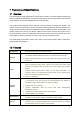
1 Features and Specifications 1.1 Overview This series NVR is a high performance network video recorder. This series product support local preview, multiple-window display, recorded file local storage, remote control and mouse shortcut menu operation, and remote management and control function. This series product supports centre storage, front-end storage and client-end storage. The monitor zone in the front-end can be set in anywhere.
• Backup Network Management Peripheral Equipment Management • • • • • • Auxiliary • • • • Support network backup, USB2.0 record backup function, the recorded files can be saved in network storage server, peripheral USB2.0 device, burner and etc. Supervise NVR configuration and control power via Ethernet. Support management via WEB. Support peripheral equipment management such as protocol setup and port connection. Support transparent data transmission such as RS232 (RS-422), RS485 (RS-485).
Wireless antenna AP N/A Window Split 1/4/9-window Multiple-chann el Playback Max 16-channel D1/8-channel 720P/4-channel 1080P playback. Alarm Input N/A Alarm Output N/A Storage One built-in SATA port. RS232 Port N/A RS485 port N/A USB2.0 Port One peripheral USB2.0 port. Network Connection One RJ45 10/100Mbps self-adaptive Ethernet port. Power Port One power port, power adapter. Input DC 12V. Power Button No on/off button. Connect to the power cable to boot up.
Parameter Specifications NVR708S2-P/NVR716S2-P/NVR732S2-P System Resources Max support 32-ch standard definition with the transmission rate of 2Mbps for each channel; 16-channel 720P, with the transmission rate of 4Mbps for each channel; 8-channel 1080P, with the transmission rate of 8Mbps for each channel; Support 20 online users at the same time, The image delay time of each channel is under 500ms.
Power Button One power button in the rear panel. Power Button One power button in the front panel. IR Remote Control Receiver Support IR remote control Clock Built-in clock. Indication Light z z z z z Power Consumption <12W(Exclude HDD) Working Temperature 0℃~+50℃ Working Humidity 10℅-90℅ Air pressure 86kpa-106kpa Dimension 375mm×287mm×52mm Weight 1.5~2.5 KG(Exclude HDD) Installation Desk installation 1.3.3 16 record status indication lights One power status indication light.
Video Input 8/16/32-ch network compression video input HDMI 1-ch HDMI output. Audio Input 1-ch bidirectional audio input Audio Output 1-ch bidirectional talk output. Window Split 1/4/8/9/16/25/36-window Multiple-chann el Playback Max 16-channel playback. Alarm Input 16-ch alarm input 6-ch alarm output Alarm Output Storage Relay output. Relay (DC 30V 1A,AC 125V Including one controllable DC +12V output. 0.5A(Activation output)) 8 built-in SATA ports.
Weight 5.5~6.
2 Front Panel and Rear Panel 2.1 Front Panel 2.1.1 NVR4i/NVR8i/ NVR4i-P/NVR8i-P Series The front panel is shown as in Figure 2-1. Figure 2-1 Please refer to the following sheet for detailed information. Icon 2.1.2 Name Function Power indicator light The blue light becomes on when the power connection is OK. Network status indicator light The blue light becomes on when the network connection is abnormal or offline.
Shift Up/1 Down/4 In textbox, click this button to switch between numeral, English(Small/Capitalized),donation and etc. Shift Activate current control, modify setup, and then move up and down. S、T Increase/decrease numeral. Assistant function such as PTZ menu. In text mode, input number 1/4 (English character G/H/I) Shift current activated control, Left/2 Right/3 W ESC ESC X When playback, click these buttons to control playback bar.
Reverse/Pau se/6 W f Play Next/9 Play/Pause /5 f In normal playback or pause mode, click this button to reverse playback In reverse playback, click this button to pause playback. In playback mode, playback the next video In menu setup, go to down ward of the dropdown list. In text mode, input number 9 (English character W/X/Y/Z) In normal playback click this button to pause playback In pause mode, click this button to resume playback. In text mode, input number 5(English character J/K/L).
0 In text mode, input number 0. It is the space button. 1,. In text mode, input number 1 and denotation. 2ABC Number and Character 3DEF In text mode, input number 3(English character D/E/F) 4GHI 5JKL 6MNO In text mode, input number 4 (English character G/H/I) In text mode, input number 5(English character J/K/L). In text mode, input number 6 (English character M/N/O) 7PQRS In text mode, input number 7 (English character P/Q/R/S). 8TUV In text mode, input number 8 (English character T/U/V).
Backspace function: in numeral control or text control, press it for 1.5seconds to delete the previous character before the cursor. In motion detection setup, working with Fn and direction keys to realize setup. In text mode, click it to switch between numeral, English character(small/capitalized) and etc. Realize other special functions. Fast play Play previous Reverse/Pau se Various fast speeds and normal playback.
IR Receiver It is to receive the signal from the remote control. IR Shuttle(outer ring) In real-time monitor mode it works as left/right direction key. Playback mode, counter clockwise to forward and clock wise to backward. Jog(inner dial) Up/down direction key. Playback mode, turn the inner dial to realized frame by frame playback. (Only applies to some special versions.) CD-ROM button Pop-up or insert the CD. 2.2 Rear Panel 2.2.
Port Name VGA PoE PORTS Connection VGA video output port VGA VGA video output port. Output analog video signal. It can connect to the monitor to view analog video. GND / Alarm input port GND port. Power port input / Power port. Input 12V DC. Power port input / Switch power port. Input DC 48V. / Built-in Switch supports PoE function. 4 PoE ports The 4 PoE ports series product supports total 48V 50W. USB 2.0 port / USB 2.0 port. Conenct to mouse. Wireless AP 2.2.
1-8 Port Name Connection Function Alarm input port 1-8. I/O port z z NO1~NO3 Alarm input port ground end Alarm input ground end. Alarm output z port 1~3 C1~C3 z z A B There are two groups. The first group is from port 1 to port 4; the second group is from port 5 to port 8. They are to receive the signal from the external alarm source. There are two types; NO (normal open)/NC (normal close).
MIC OUT 2.2.3 Port Name Connection Function Audio output port / Audio output port. It is to output the analog audio signal to the devices such as the sound box. z Bidirectional talk output. z Audio output on 1-window video monitor. z Audio output on 1-window video playback. NVR708X2/NVR716X2/NVR732X2 Series The rear panel is shown as below. See Figure 2-7. Figure 2-7 Please refer to the following sheet for detailed information.
Port Name Connection Function C2,Group 3:port NO3~C3, Group 4:port NO4~C4, Group 5: port NO5, C5, NC5).Output alarm signal to the alarm device. Please make sure there is power to the external alarm device. C1 to C5 NC5 A B RS485 (RS-485) communication port z NO: Normal open alarm output port. z C: Alarm output public end. z NC: Normal close alarm output port. RS485_A port. It is the cable A. You can connect to the control devices such as speed dome PTZ. RS485_B.It is the cable B.
z z device can connect to the NO/C/NC port. For the NO alarm device, please connect to the NO/C ports. For the NC alarm device, please connect to the NC/C ports. Please note the NO/C ports are for NO alarm device only. Open Web, and go to the Alarm setup interface to set the alarm input and output. The alarm 01 is corresponding to the first channel of the device I/O port and so on.
Listening Operation At the PC-end, speak via the speaker or the pickup, and then you can get the audio from the earphone or sound box at the device-end. See Figure 2-10. Figure 2-10 2.5 Mouse Operation Please refer to the following sheet for mouse operation instruction. Left click mouse When you have selected one menu item, left click mouse to view menu content. Modify checkbox or motion detection status. Click combo box to pop up dropdown list In input box, you can select input methods.
Right click mouse In real-time monitor mode, pops up shortcut menu. Press middle button In numeral input box: Move mouse Select current control or move control Drag mouse Select motion detection zone Exit current menu without saving the modification. Increase or decrease numeral value. Switch the items in the check box. Page up or page down Select privacy mask zone.
3 HDD Installation Important: Please turn off the power before you replace the HDD. The pictures listed below for reference only. For the first time install, please be aware that whether the HDDs have been installed. You can refer to the Appendix for recommended HDD brand. Please use HDD of 7200rpm or higher. Usually we do not recommend the PC HDD. Please follow the instructions below to install hard disk. 3.1 NVR4i/NVR8i/NVR4i-P/NVR8i-P Series 1. Loosen the screws of the upper cover and side panel. 2.
1. Loosen the screws of the upper cover and side panel. 4. Turn the device upside down 2. Fix four screws in the HDD (Turn just three rounds). 5. Fix the HDD firmly. and then turn the screws in 3. Place the HDD in accordance with the four holes in the bottom. 6. Connect the HDD cable and power cable. firmly. 7. Put the cover in accordance 8. Secure the screws in the rear with the clip and then place the panel and the side panel. upper cover back. 3.
② Put the HDD to the HDD bracket in the chassis and then line up the four screws to the four holes in the HDD. Use the screwdriver to fix the screws firmly to secure HDD on the HDD bracket ③ Connect to the HDD data cable to the main board and the HDD port respectively. Loosen the power cable of the chassis and connect another end of the power cable to the HDD port. ④ After connect the cable, put the front cover back to the device and then fix screws of the rear panel.
4 GUI Operation Connect the device to the monitor and then connect a mouse and power cable. Click the power button at the rear panel and then boot up the device to view the video output. You can use the mouse to implement some GUI operation. 4.1 Login After device booted up, the system is in multiple-channel display mode. See Figure 4-1.Please note the displayed window amount may vary. The following figure is for reference only. Figure 4-1 System consists of four accounts: z z z Username: admin.
Figure 4-2 You can overlay the corresponding date, time and channel name on each screen. You can refer to the following sheet for channel record or alarm status information. 1 Recording status 3 Video loss 2 Motion detection 4 Camera lock Preview Control The preview control function has the following features. z Support preview playback. In the preview desktop, system can playback previous 5-60 minutes record of current channel. Please go to the Main Menu->General to set real-time playback time.
real-time playback time. System may pop up a dialogue box if there is no such record in current channel. It is to zoom in specified zone of current channel. It supports zoom in function of multiple-channel. 2 Digital zoom and the The selected area has an icon as . free area is shown as an icon as It is to backup the video of current channel to the USB2.0 device. System can not backup the video of multiple-channel at the same time.
Here you can set local playback window, PTZ control, video color, search records, remote device and etc. The local playback window includes 1/4/8/9/16. You can set the detail channel amount in 1/4-window. Figure 4-4 4.3 Main Menu After you logged in, the system main menu is shown as below. See Figure 4-5. There are total seven icons: search, Information, setting, remote device, backup, advanced and shutdown. Move the cursor to highlight the icon, then double click mouse to enter the sub-menu.
2 1 3 4 11 7 6 5 10 8 9 12 Figure 4-6 Please refer to the following sheet for more information. SN 1 2 Name Display window Search type Function z z Here is to display the searched picture or file. Support 1/4/9/16-window playback. z Here you can select to search the picture or the recorded file. z You can select to play from the read-write HDD, from peripheral device or from redundancy HDD.
selection pane. In 9-window playback mode, you can switch between 1-8 and 9-16 channels. In 16-window playback mode, you can switch between1-16 and 17-32 channels. z The time bar will change once you modify the playback mode or the channel option. z Double click it, you can view the picture/record file list of current day. z The file list is to display the first channel of the record file. z The system can display max 128 files in one time. Use the S/T or the mouse to view the file.
│X to begin frame by frame playback. In frame by frame playback mode, click ►/ to restore normal playback. ► Slow play In playback mode, click it to realize various slow play modes such as slow play 1, slow play 2, and etc. Fast forward In playback mode, click to realize various fast play modes such as fast play 1,fast play 2 and etc. Note: The actual play speed has relationship with the software version.
type z 13 Smart search z z z z When system is playing, you can select a zone in the window to begin motion detect. Click the motion detect button to begin play. Current button is null once the motion detect play has begun. The system will take the whole play zone as the motion detect region by default. The motion detect play stopped once you switch the play file. Operations such as set time bar, click the play button, or any file list operation will stop current motion detect play.
4.5.1 HDD Information Here is to list hard disk type, total space, free space, and status. See Figure 4-8. ○ means current HDD is normal.. - means there is no HDD. If disk is damaged, system shows as “?”. Please remove the broken hard disk before you add a new one. Figure 4-8 In Figure 4-8, click view record d time button, HDD record time information interface is shown as in Figure 4-9. Figure 4-9 Parameter Function SATA 1-4 here means there are 4 HDDS.
Free space The HDD free capacity. Status HDD can work properly or not. Bad track Display there is bad track or not. Page up Click it to view previous page. Page down Click it to view the next page. View recording time Click it to view HDD record information (file start time and end time). View HDD type and capability Click it to view HDD property, status and etc, 4.5.2 BPS Here is for you to view current video data stream (KB/s) and occupied hard disk storage (MB/h). See Figure 4-10.
4.5.3 Log Here is for you to view system log file. System lists the following information. See Figure 4-12. Log types include system operation, configuration operation, data management, alarm event, record operation, log clear and etc. z Start time/end time: Pleased select start time and end time, then click search button. You can view the log files in a list. System max displays 100 logs in one page. It can max save 1024 log files.
4.5.4 Version Here is for you to view some version information. See Figure 4-14. z Channel z Alarm in z Alarm out z System version: z Build Date z Web z Serial number Figure 4-14 4.5.5 Online Users Here is for you manage online users connected to the local device. See Figure 4-15. You can disconnect one user or block one user if you have proper system right. Figure 4-15 4.5.6 Remote Device Information Here you can view the channel status of the remote device, connection log and etc.
Figure 4-16 Connection log: In this interface, you can search the IPC log information of the corresponding channel. It includes IPC online, offline and etc. See Figure 4-17. Figure 4-17 4.5.7 Network Info In this interface, you can see network test and network load information. 4.5.7.1 Network Test Network test interface is shown as in Figure 4-18. Destination IP: Please input valid IPV4 address and domain name. Test: Click it to test the connection with the destination IP address.
connection and etc. Network Sniffer backup: Please insert USB2.0 device and click the Refresh button, you can view the device on the following column. You can use the dropdown list to select peripheral device. Click Browse button to select the snap path. The steps here are same as preview backup operation. You can view all connected network adapter names (including Ethernet, PPPoE, WIFI, and 3G), you can click the button on the right panel to begin Sniffer. Click the grey stop button to stop.
Figure 4-19 4.6 Setting In main menu, highlight setting icon and double click mouse. System setting interface is shown as below. See Figure 4-20. Figure 4-20 Important Please note you need to have the proper right to implement the following operation. 4.6.1 General General setting includes the following items. See Figure 4-21. z System time: Here is for you to set system time z Date format: There are three types: YYYYY-MM-DD: MM-DD-YYYYY or DD-MM-YYYY.
z z z z z z z z z z z z z z z z DST: Here you can set DST time and date. Please enable DST function and then click set button. You can see an interface is shown as in Figure 4-22. Here you can set start time and end time by setting corresponding week setup. In Figure 4-22, enable date button, you can see an interface is shown as in Figure 4-23. Here you can set start time and end time by setting corresponding date setup. Time format: There are two types: 24-hour mode or 12-hour mode.
Figure 4-21 Figure 4-22 Figure 4-23 Figure 4-24 40
Figure 4-25 4.6.2 Encode Encode setting includes the following items. See Figure 4-26. Please note some series do not support extra stream. z Channel: Select the channel you want. z Type: Please select from the dropdown list. There are three options: regular/motion detect/alarm. You can set the various encode parameters for different record types. z Compression: System supports H.264, MPEG4, MJPEG and etc. z Resolution: The mainstream resolution type is IPC’s encoding config.
Please highlight icon to select the corresponding function.
Figure 4-29 4.6.3 Schedule In the main menu, from setting to schedule, you can go to schedule menu. See Figure 4-30. z Channel: Please select the channel number first. You can select “all” if you want to set for the whole channels. z Week day: There are eight options: ranges from Saturday to Sunday and all. z Pre-record: System can pre-record the video before the event occurs into the file. The value ranges from 1 to 30 seconds depending on the bit stream.
Figure 4-30 4.6.3.1 Quick Setup Copy function allows you to copy one channel setup to another. After setting in channel 1, click Copy button, you can go to interface Figure 4-31. You can see current channel name is grey such as channel 1. Now you can select the channel you wan to paste such as channel 5/6/7. If you wan to save current setup of channel 1 to all channels, you can click the first box “ALL”. Click the OK button to save current copy setup.
z Data bit: You can select proper data bit. The value ranges from 5 to 8. z Stop bit: There are three values: 1/1.5/2. z Parity: there are five choices: none/odd/even/space mark. System default setup is: z Function: Console z Baud rate:115200 z Data bit:8 z Stop bit:1 z Parity: None After completing all the setups please click save button, system goes back to the previous menu. Figure 4-32 4.6.5 Network Here is for you to input network information. See Figure 4-33.
z z HTTP port: Default value is 80. RTSP port: Default value is 554. Important: System needs to reboot after you changed and saved any setup of the above four ports. Please make sure the port values here do not conflict. z Max connection: system support maximal 20 users. 0 means there is no connection limit. z MTU: It is to set MTU value of the network adapter. The value ranges from 1280-7200 bytes. The default setup is 1500 bytes.
Figure 4-34 4.6.5.2 IP Filter IP filter interface is shown as in Figure 4-35. You can add IP in the following list. The list supports max 64 IP addresses. System supports valid address of IPv4 and IPv6. Please note system needs to check the validity of all IPv6 addresses. After you enabled trusted sites function, only the IP listed below can access current NVR. If you enable blocked sites function, the following listed IP addresses can not access current NVR.
Figure 4-35 4.6.5.3 NTP Setup You need to install SNTP server (Such as Absolute Time Server) in your PC first. In Windows XP OS, you can use command “net start w32time” to boot up NTP service. NTP setup interface is shown as in Figure 4-36. z Host IP: Input your PC address. z Port: This series NVR supports TCP transmission only. Port default value is 123. z Update interval: minimum value is 1. Max value is 65535. (Unit: minute) z Time zone: select your corresponding time zone here.
Brazil GMT-3 Middle Atlantic Time GMT-2 Figure 4-36 4.6.5.4 Multicast Multiple-cast setup interface is shown as in Figure 4-37. Figure 4-37 Here you can set a multiple cast group. Please refer to the following sheet for detailed information. z IP multiple cast group address -224.0.0.0-239.255.255.255 -“D” address space z The higher four-bit of the first byte=”1110” z Reserved local multiple cast group address -224.0.0.0-224.0.0.255 -TTL=1 When sending out telegraph -For example 224.0.0.
Except the above mentioned addresses of special meaning, you can use other addresses. For example: Multiple cast IP: 235.8.8.36 Multiple cast PORT: 3666. After you logged in the Web, the Web can automatically get multiple cast address and add it to the multiple cast groups. You can enable real-time monitor function to view the view. Please note multiple cast function applies to special series only. 4.6.5.5 PPPoE PPPoE interface is shown as in Figure 4-38.
Figure 4-39 Please note NNDS type includes: CN99 DDNS, NO-IP DDNS, Quick DDNS, and Dyndns DDNS. All the DDNS can be valid at the same time, you can select as you requirement. Quick DDNS function shall work with special DDNS server and special Professional Surveillance Software (PSS). Quick DDNS and Client-end Introduction 1) Background Introduction Device IP is not fixed if you use ADSL to login the network. The DDNS function allows you to access the NVR via the registered domain name.
z z Do not register frequently. The interval between two registrations shall be more than 60 seconds. Too many registration requests may result in server attack. System may take back the domain name that is idle for one year. You can get a notification email before the cancel operation if your email address setup is OK. 4.6.5.7 UPNP The UPNP protocol is to establish a mapping relationship between the LAN and the WAN. Please input the router IP address in the LAN in Figure 4-33.
Figure 4-40 Figure 4-41 4.6.5.8 WIFI Setting You can view the WIFI connection status in the Network Setting interface. See Figure 4-42. You can view current connection status and IP address if there is a connection. Figure 4-42 The WIFI interface is shown as below. See Figure 4-43.
z z z z Auto connect WIFI: Check the box here, system automatically connects to the previous WIFI hotspot. Refresh: You can click it to search the hotspot list again. It can automatically add the information such as the password if you have set it before. Disconnect: Here you can click it to turn off the connection. Connect: Here you can click it to connect to the hotspot. System needs to turn off current connection and then connect to a new hotspot if there is connection of you selected one.
Figure 4-45 z WIFI working status: Here you can view current connection status. Please note: z After successful connection, you can see WIFI connection icon at the top right corner of the preview interface. z When the hotspot verification type is WEP, system displays as AUTO since the device can not detect its encryption type. z System does not support verification type WPA and WPA2. The display may become abnormal for the verification type and encryption type.
Title: Please input email subject here. System support English character and Arabic number. Max 32-digit. z Receiver: Please input receiver email address here. System max supports 3 email boxes. z SSL enable: System supports SSL encryption box. z Interval: The send interval ranges from 0 to 3600 seconds. 0 means there is no interval. z Health email enable: Please check the box here to enable this function. This function allows the system to send out the test email to check the connection is OK or not.
Figure 4-49 You can use a PC or FTP login tool to test setup is right or not. For example, you can login user ZHY to FTP://10.10.7.7 and then test it can modify or delete folder or not. See Figure 4-50. H140TU UTH Figure 4-50 System also supports upload multiple NVRs to one FTP server. You can create multiple folders under this FTP. In Figure 4-33, select FTP and then double click mouse. You can see the following interface. See Figure 4-51.
Figure 4-51 Figure 4-52 4.6.5.11 Alarm center Interface is pre-reserved for the users to develop this function. 4.6.5.12 SNMP SNMP is an abbreviation of Simple Network Management Protocol. It provides the basic network management frame of the network management system. The SNMP widely used in many environments. It is used in many network device, software and system. You can set in the following interface. See Figure 4-53.
Please enable the SNMP function. Use the corresponding software tool (MIB Builder and MG-SOFT MIB Browser. You still need two MIB file: BASE-SNMP-MIB, NVR-SNMP-MIB) to connect to the device. You can get the device corresponding configuration information after successfully connection. Please follow the steps listed below to configure. z In Figure 4-53, check the box to enable the SNMP function. Input the IP address of the PC than is running the software in the Trap address.
4) Now you can boot up the proxy server. When you see the network status is Y, it means your registration is OK. You can view the proxy server when the device is online. Important The server IP address can also be domain. But you need to register a domain name before you run proxy device server. 4.6.6 Alarm In the main menu, from Setting to Alarm, you can see alarm setup interface. See Figure 4-55. z Alarm in: Here is for you to select channel number. z Event type: There are four types.
z z z z z z z z z Alarm output: The number here is the device alarm output port. You can select the corresponding ports(s) so that system can activate the corresponding alarm device(s) when an alarm occurred. Latch: When the anti-dither time ended, the channel alarm you select in the alarm output may last the specified period. The value ranges from 1 to 300 seconds. This function is not for other alarm activation operations. The latch is still valid even you disable the alarm event function directly.
Figure 4-55 Figure 4-56 Figure 4-57 62
Figure 4-58 For the 32-channel series product, the alarm interface and PTZ setup is shown as below. See Figure 4-59 and Figure 4-60. Figure 4-59 Figure 4-60 4.6.7 Detect Go to Detect Menu In the main menu, from Setting to Detect, you can see motion detect interface. See Figure 4-61.There is three detection types: motion detection, video loss, camera masking.
z z detection region setup. You can see motion detect icon if current channel has enabled motion detect alarm. You can drag you mouse to set motion detect region without Fn button. Please click OK button to save current region setup. Right click mouse to exit current interface. 4.6.7.1 Motion Detect Detection menu is shown as below. See Figure 4-61. z Event type: From the dropdown list you can select motion detection type. z Channel: Select a channel from the dropdown list to set motion detect function.
save button, system goes back to the previous menu. Note: In motion detection mode, you can not use copy/paste to set channel setup since the video in each channel may not be the same. In Figure 4-62, you can left click mouse and then drag it to set a region for motion detection. Click Fn to switch between arm/withdraw motion detection. After setting, click enter button to exit.
Figure 4-64 Figure 4-65 4.6.7.2 Video Loss In Figure 4-61, select video loss from the type list. You can see the interface is shown as in Figure 4-66.This function allows you to be informed when video loss phenomenon occurred. You can enable alarm output channel and then enable show message function. You can refer to chapter 4.6.7.1Motion detect for detailed information. Tips: You can enable preset/tour/pattern activation operation when video loss occurs. Figure 4-66 4.6.7.
environments light change, the system can alert you to guarantee video continuity. Camera masking interface is shown as in Figure 4-67. You can enable alarm output channel and then enable show message function. You can refer to chapter 4.6.7.1Motion detect for detailed information. Tips: You can enable preset/tour/pattern activation operation when video loss occurs.
z z z z z Address: Default address is 1. Baud rate: Select corresponding baud rate. Default value is 9600. Data bit: Select corresponding data bits. Default value is 8. Stop bit: Select corresponding stop bits. Default value is 1. Parity: There are three options: odd/even/none. Default setup is none. Figure 4-68 If you are connecting to network PTZ, the PTZ type shall be remote. See Figure 4-69. Figure 4-69 After completing all the setting please click save button.
Please click icon and to adjust zoom, focus and iris. Figure 4-70 In Figure 4-70, please click direction arrows to adjust PTZ position. There are total 8 direction arrows. Figure 4-71 Here is a sheet for you reference. Name Function key function Zoom Wide Focus Near Iris Close 4.6.9 Shortcut key Function key function Far Shortcut Key │_ Far ►│ W Open f Display Display setup interface is shown as below. See Figure 4-72. z Transparency: Here is for you to adjust transparency.
Figure 4-72 In Figure 4-72, click modify button after channel. You can see an interface shown as in Figure 4-73. Please note all your modification here applies to local end only. You need to refresh web or client-end to get the latest channel name. System max support 25-digital character. Figure 4-73 4.6.10 Default Click default icon, system pops up a dialogue box. You can highlight to restore default factory setup.
z z Display Channel name Please highlight icon to select the corresponding function. After all the setups please click OK button, system goes back to the previous menu. Warning! System menu color, language, time display mode, video format, IP address, user account will not maintain previous setup after default operation! 4.6.11 Remote Device Important Do not connect the switch to the PoE port, otherwise the connection may fail! 4.6.11.
Figure 4-76 The remote device interface is shown as in Figure 4-77. z IP search: Click it to search IP address. z Add: Click it to connect to the selected device and add it to the Added device list. Support Batch add. z Show filter: You can use it to display the specified devices from the added device. z IPC config: Double click the z z interface. See Figure 4-78. Gain mode: It is to set video noise. Check Auto, system automatically sets video gain.
Figure 4-77 Figure 4-78 Click the Manual Add button; you can go to the following interface. See Figure 4-79. This series product max supports 32-channel standard definition video/high definition non-real-time video and the transmission rate is 1Mbps per channel. It can also max supports 4-channel high definition video and the transmission rate is 8Mbps. The delay time of each channel is below 500ms. Model System Performance 4-ch series Max support 4-channel video.
Total resources:400/480fps@D1,200/240fps@720P.100/120@1080P. 8-ch series Max support 8-channel video. Total resources:400/480fps@D1,200/240fps@720P.100/120@1080P. 16-ch series Max support 16-channel video. Total resources:400/480fps@D1,200/240fps@720P.100/120@1080P. 32-ch series Max support 32-channel standard definition video. Support 8-channel 1080p/5Mbps (extra stream D1/1Mbps), 16-channel 720p/2Mbps (extra CIF/640kbps), 32-channel D1/1Mbps.
Figure 4-80 Figure 4-81 4.7 Advanced Double click advanced icon in the main window, the interface is shown as below. See Figure 4-82.There are total eight function keys: HDD management, alarm output, abnormity, manual record, account, auto maintenance, TV adjust and video matrix.
Figure 4-82 4.7.1 HDD Management Here is for you to view and implement hard disk management. See Figure 4-83. You can see current HDD type, status, capacity and record time. When HDD is working properly, system is shown as O. When HDD error occurred, system is shown as X. z Alarm set: Click alarm set button, the interface is shown as below. See Figure 4-84. (This interface is just like the abnormality setup). Please refer to chapter 4.7.2 for detailed information.
Figure 4-84 For the HDD group setup operation, please note: z Each channel’s records can be stored into the specified HDD Group. z Each HDD Group is corresponding to several hard disks, while one hard disk is only included in one HDD Group. z Each channel is only corresponding with one HDD Group, while one HDD Group can store records from several channels. z HDD Group is only available for read-write HDD and self-defined disks, other types of hard disks cannot be set as HDD Group.
Figure 4-85 Channels Setting Click the button named with “Channels Settings” at the top right corner of the Figure 4-83, system will pop up an interface shown as in Figure 4-86. You can set HDDs for main stream, extra stream and snap pictures respectively. The main stream and extra stream of one channel can be saved to different groups. Channel: It is to display the actual channel number of current NVR. HDD Group: It is the SN of the HDD group management.
z z z z z z z Event type: There are several options for you such as disk error, no disk, disconnection, IP conflict and etc. Alarm output: Please select alarm activation output port (multiple choices). Latch: Here you can set corresponding delaying time. The value ranges from 10s-300s. System automatically delays specified seconds in turning off alarm and activated output after external alarm cancelled. Show message: system can pop up the message in the local screen to alert you when an alarm occurs.
Note: You need to have proper rights to implement the following operations. Please make sure the HDD has been properly installed. 4.7.4.1 Manual record menu Right click mouse or in the main menu, Advanced->Manual Record. Manual record menu is shown as in Figure 4-89. 4.7.4.2 Basic operation There are three statuses: schedule/manual/stop. Please highlight icon “ ○ ” to select corresponding channel. z Manual: The highest priority. After manual setup, all selected channels will begin ordinary recording.
z All channel schedule record Please highlight “ALL” after “Schedule”. See Figure 4-91. When system is in schedule recording, all channels will record as you have previously set (Main menu->Setting->Schedule). The corresponding indication light in front panel will turn on. Figure 4-91 z All channel manual record Please highlight “ALL” after “Manual.” See Figure 4-92. When system is in manual recording, all scheduled set up you have set in will be null ((Main menu->Setting->Schedule)).
Figure 4-93 4.7.5 Account Here is for you to implement account management. See Figure 4-94. Here you can: z Add new user z Modify user z Add group z Modify group z Modify password. For account management please note: z For the user account name and the user group, the string max length is 6-byte. The backspace in front of or at the back of the string is invalid. There can be backspace in the middle. The string includes the valid character, letter, number, underline, subtraction sign, and dot.
Figure 4-94 4.7.5.1 Modify Password Click password button, the interface is shown as in Figure 4-95. Here you can modify account password. Please select the account from the dropdown list, input the old password and then input the new password twice. Click the Save button to confirm current modification. For the users of user account right, it can modify password of other users. Figure 4-95 4.7.5.2 Add/Modify Group Click add group button, the interface is shown as below. See Figure 4-96.
Figure 4-96 4.7.5.3 Add/Modify User Click add user button, the interface is shown as in Figure 4-97. Please input the user name, password, select the group it belongs to from the dropdown list. Then you can check the corresponding rights for current user. For convenient user management, usually we recommend the general user right is lower than the admin account. The modify user interface is similar to Figure 4-97. Figure 4-97 4.7.
Figure 4-98 4.7.7 Config Backup The configuration file backup interface is shown as below. See Figure 4-99. This function allows you to copy current system configuration to other devices. It also supports import, create new folder, delete folder and etc function. Figure 4-99 4.8 Shutdown Double click shutdown button, system pops up a dialogue box for you to select. See Figure 4-100. z Logout menu user: log out menu. You need to input password when you login the next time.
Figure 4-100 86
5 Quick Configuration Tool 5.1 Overview Quick configuration tool can search current IP address, modify IP address. At the same time, you can use it to upgrade the device. Please note the tool only applies to the IP addresses in the same segment. 5.2 Operation Double click the “ConfigTools.exe” icon, you can see an interface is shown as in Figure 5-1. In the device list interface, you can view device IP address, port number, subnet mask, default gateway, MAC address and etc.
Select the “Open Device Web” item; you can go to the corresponding web login interface. See Figure 5-3. Figure 5-3 If you want to modify the device IP address without logging in the device web interface, you can go to the configuration tool main interface to set. In the configuration tool search interface (Figure 5-1), please select a device IP address and then double click it to open the login interface. Or you can select an IP address and then click the Login button to go to the login interface.
Figure 5-5 For detailed information and operation instruction of the quick configuration tool, please refer to the Quick Configuration Tool User’s Manual included in the resources CD.
6 Web Operation 6.1 General Introduction The device web provides channel monitor menu tree, search, alarm setup, system setup, PTZ control and monitor window. Important The following operation is based on 16-channel series device. For the 32-channel series product, there is 32-channel option. 6.1.1 Preparation Before log in, please make sure: z Network connection is right z NVR and PC network setup is right. Please refer to network setup(main z menu->setting->network) z Use order ping ***.***.***.
b) If it is your second time to insert the PoE, system can check the saved MAC address according to --- map to make sure current IPC has connected or not. If system finds the previous information and the channel is idle, system can map it to the previously used channel. Otherwise system goes to the next step. c) Thirdly, according to the --- map, system can know the previous mapping channel of current PoE port. System can select current channel if it is free.
Figure 6-2 IE Safety Setup After installation, the interface is shown as below. See Figure 6-3. Figure 6-3 Login interface Please input your user name and password. Default factory name is admin and password is admin. Note: For security reasons, please modify your password after you first login. 6.
② For the LAN mode, after you logged in, you can see the main window. See Figure 6-4. ③ ④ ① ⑤ ⑥ Figure 6-4 Main Interface There are six sections: z Section 1: Monitor channel menu tree z Section 2: System menu z Section 3: PTZ control z Section 4: Video setup and other setup z Section 5: Preview window z Section 6: Monitor window switch 6.2.1 Monitor Channel Menu Tree The monitor channel menu tree is shown as in Figure 6-5. Please note the following figure is for reference only.
Figure 6-5 Monitor Channel Menu Tree Please refer to the following sheet for detailed information. Parameter Function CAM 1 to CAM 16 channel 1 to channel 16 Open all /close all Click this button to open all video channels. Once all video channels are open, it becomes close all button. Start Dialogue You can click this button to enable audio talk. Click 【▼】 to select bidirectional talk mode. There are four options: DEFAULT, G711a,G711u and PCM.
Local play The Web can playback the saved (Extension name is dav) files in the PC-end. Click local play button, system pops up the following interface for you to select local play file. See Figure 6-6. Figure 6-6 Refresh Click this button to refresh monitor channel name. Please left click one monitor to view real-time video, the monitor window is shown as in Figure 6-7. Figure 6-7 Real-time Monitor Please refer to the following sheet for monitor window parameter information.
6.2.2 Change show mode Resize or switch to full screen mode. Local record When you click local record button, the system begins recording. The recorded file is saved to system folder: \ RecordDownload(default). Snapshot You can snapshoot important video. All images are memorized in system folder: \ picture download (default). Audio Turn on or off audio. Close video Close video in current window. System Menu System menu is shown as in Figure 6-8. Please refer to chapter 6.
You can click this icon to display or hide the PTZ control platform. Figure 6-10 PTZ Interface Click PTZ set button, the interface is shown as in Figure 6-11.
Please refer to the following sheet for PTZ setup information. Parameter Function Scan z z Move the camera to you desired location and then click left limit button. Then move the camera again and then click right limit button to set a right limit. Preset Use direction keys to move the camera to your desired location and then input preset value. Click add button, you have set one preset. Tour z z z Input auto tour value and preset value. Click add button, you have added one preset in the tour.
It is to adjust monitor video contrast ness. All the operation here applies to WEB end only. It is to adjust monitor video saturation. It is to adjust monitor video hue. Reset Restore system default value. Click more button, the interface is shown as in Figure 6-13. Figure 6-13 Color and More Please refer to the following sheet for detailed information. Parameter Function More Picture Path Click picture path button, system pops up an interface for you to modify path.
Figure 6-14 Please refer to the following contents for LAN and WAN login difference. 1) In the WAN mode, system opens the main stream of the first channel to monitor by default. The open/close button on the left pane is null. 2) You can select different channel and different monitor mode at the bottom of the interface. See Figure 6-15. Figure 6-15 Important The window display mode and the channel number are by default. For example, for the 16-channel, the max window split mode is 16.
main stream. A stands for 4) When you switch from Monitor to Search or Configuration, system pops a dialogue box asking you leave current interface or not. See Figure 6-16.Click the OK button, system will close current monitor window. For example, you click the Config button when you are monitoring, system pos up a following dialogue. Click the OK button, system closes current monitor interface and open the configuration interface.
Figure 6-17 Version Information 6.4.1.2 HDD information Here you can view local storage status such as free capacity and total capacity. See Figure 6-18. Figure 6-18 HDD Information 6.4.1.3 Log Here you can view system log.
Figure 6-19 Log Please refer to the following sheet for log parameter information. Parameter Function Type Log types include: system operation, configuration operation, data management, alarm event, record operation, user management, log clear and file operation. Start time Set time to start search. Finish time Set time to finish search Search You can select log type from the drop down list and then click search button to view the list.
Figure 6-20 General Setup Figure 6-21 DST Figure 6-22 DST Please refer to the following sheet for detailed information. Parameter Function System Time Here is for you to modify system time. Please click Save button after your completed modification Sync PC You can click this button to save the system time as your PC current time. Data Format Here you can select data format from the dropdown list.
Data Separator Please select separator such as – or /. Time Format There are two options: 24-H and 12-H. DST Here you can set day night save time begin time and end time. See Figure 6-21and Figure 6-22. Language Here you can view the system current language. You can select from the dropdown list. HDD Full There are two options: stop recording or overwrite the previous files when HDD is full. Pack Duration Here you can select file size. The value ranges from 1 to 120 (minute).
Audio / video For the main stream, recorded file only contains video by default. You need to draw a circle here to enable audio function. For extra stream, you need to draw a circle to select the video first and then select the audio if necessary. Main code stream types are D1/HD1/2CIF/CIF/QCIF Resolution Channel 1~16 extra code stream supports CIF/QCIF. Frame rate PAL: 1f/s-25f/s;NTSC: 1f/s-30f/s There are two options: VBR and CBR. Bit rate Please note, you can set video quality in VBR mode only.
Figure 6-25 Schedule Time Figure 6-26 Copy Figure 6-27 Please refer to the following sheet for detailed information. Parameter Function Channel Please select a channel first.
Parameter Function Pre-record Please input pre-record value here. When alarm record or motion detection record occurs, system can record the several seconds video before activating the record operation into the file. (Depends on data size). Setup In Figure 6-24, click set button, you can go to the corresponding setup interface. See Figure 6-25. Please set schedule period and then select corresponding record type: schedule, motion detection, and alarm.
Parameter Function RS232 There is only one option COM 01, corresponding to RS232. Function Console is for debug. Control keyboard: Switch between RS232 and control keyboard. Network keyboard: COM control protocol. You can use network keyboard to control NVR via COM. Transparent COM: Network user can communicate with RS232 COM device. PTZ matrix: PTZ matrix protocol. You can use the device to control the PTZ matrix. Data Bit The value ranges from 5 to 8. Stop Bit There are three options: 1/2.
Parameter Function MAC Address The host in the LAN can get a unique MAC address. It is for you to access in the LAN. It is read-only. IP Address Here you can use up/down button (ST) or input the corresponding number to input IP address. Then you can set the corresponding subnet mask the default gateway. Subnet Prefix The input value ranges from 0 to 128. It is to mark a specifi network MAC address. Usually it includes an organization multiple-level.
Parameter Remote host Function PPPOE Input the user name and password which ISP(Internet service supplier) provided and chose enable. Reboot system after configuration is saved and the device will auto connect to Internet. The IP address is the WAN IP. There are two conditions for reboot, 1. The user must have the authority to reboot device. 2. There is no user login the system menu on the local end After PPPOE dial succeed, get the current IP address and visit this IP address via WEB.
Parameter Function Subject Input email subject here. Max 32-digit. Address Input receiver email address here. Max input three addresses. Interval Please input the send interval value here. DDNS The DDNS interface is shown as in Figure 6-32. Figure 6-32 DDNS Please refer to the following sheet for detailed information. Parameter Function Server Type You can select DDNS protocol from the dropdown list and then enable DDNS function. Server IP DDNS server IP address Server Port DDNS server port.
works with the device from the manufacturer so that it can add the extension function. 2) Function Introduction The private DDNS client has the same function as other DDNS client end. It realizes the bonding of the domain name and the IP address. Right now, current DDNS server is for our own devices only. You need to refresh the bonding relationship of the domain and the IP regularly. There is no user name, password or the ID registration on the server.
Figure 6-34 NAS Setup Please refer to the following sheet for detailed information. Parameter Function NAS enable Please select network storage protocol and then enable NAS function. The network storage protocol includes FTP. Server IP Input remote storage server IP address. Port Input Remote storage server port number. User Name Log in user account. File length The max files length when you transfer the file. When the input value is 0, then system upload the whole files.
Here you can realize network time synchronization. Please enable current function and then input server IP, port number, time zone and time. Figure 6-35 NTP Please refer to the following sheet for detailed information. Parameter Function Enable Enable NTP function or not. Server IP Server IP address Port Server port. System supports TCP only and default port value is 123. Time Zone Device current time zone. Update Interval Time update interval value.
Figure 6-36 Alarm Centre UNPN Go to the UPnP interface, you can see an image is shown as in Figure 6-37. It allows you to establish the mapping relationship between the LAN and the public network. Here you can also add, modify or remove UPNP item. Figure 6-37 UNPN SNMP The SNMP interface is shown as in Figure 6-38. SNMP is an abbreviation of Simple Network Management Protocol. It provides the basic network management frame of the network management system. The SNMP widely used in many environments.
Please refer to chapter 4.6.5.12 SNMP for detailed information. Figure 6-38 SNMP 6.4.2.6 Alarm Alarm setup interface is shown as in Figure 6-39.
Figure 6-40 PTZ Setup Figure 6-41 Please refer to the following sheet for detailed information. Parameter Function Event Type Event type: There are four types. Local input/network input/IPC external/IPC offline alarm. Local input alarm: The alarm signal system detects from the alarm input port. Network input alarm: It is the alarm signal from the network. IPC external alarm: It is the on-off alarm signal from the front-end device and can activate the local NVR.
Parameter Function Type There are two options: normal open and normal close. NO becomes activated in low voltage, NC becomes activated in high voltage. Period Alarm record function becomes activated in the specified periods. There are six periods in one day. Please draw a circle to enable corresponding period. Select date. If you do not select, current setup applies to today only. You can select all week column to apply to the whole week.
signal which meets the senility standard that is previously set. See Figure 6-42.
Figure 6-42 Detect Please refer to the following sheet for detailed information. Parameter Function Event type Motion detect, video loss and video masking Channel Select a channel from the dropdown list to set motion detect, video loss and vid masking function. Sensitivity System supports 6 levels. The sixth level has the highest sensitivity. Enable button Check the box to enable this function. There are PAL22X18/NTSC22X15 small zones. Region Blue area is the detection zone.
Please note, before operation please make sure you have set speed dome address and the NVR and speed dome connection is OK. Figure 6-43 PTZ Please refer to the following sheet for detailed information. Parameter Function Channel You can select monitor channel from the dropdown list. . Protocol Select the corresponding dome protocol.(such as PELCOD) Address Set corresponding dome address. Default value is 1.
Figure 6-44 Default and Backup Please refer to the following sheet for detailed information. Parameter Function Select All Restore factory default setup. Export Configuration Export system configuration to local PC. Import Configuration Import configuration from PC to the system. 6.4.3 Advanced 6.4.3.1 HDD Management Please select the storage device first and then you can see the items on your right become valid. You can check the corresponding item here. See Figure 6-45.
Please refer to the following sheet for detailed information. Parameter Function Format Clear data in the HDD. Read/write Set current HDD as read/write Read only Set current HDD as read. Redundant Set current HDD as redundant HHD. Recover Fix the HDD error. Right now the device does not support this function. 6.4.3.2 Abnormity The interface is shown as in below. See Figure 6-46 and Figure 6-47.
Parameter Function Event Type The abnormal events include: no disk, no space, disk error, offline, IP conflict. You need to draw a circle to enable this function. Threshold: It refers to the HDD free space threshold. Normal Out The corresponding alarm output channel when an alarm occurs. Latch The alarm output can delay for the specified time after alarm stops. The value ranges from 10s to 300s.
Please refer to the following sheet for detailed information. Parameter Function Alarm output The alarm output channel may vary. The interface here is for reference only. Please click the corresponding number and then click the trigger button. Trigger Enable/disable alarm output. Please note once you activate an alarm manually, you need to click the output channel number again and then click trigger button to disable it. Otherwise the alarm can not be cancelled. Refresh Search alarm output status.
Figure 6-50 Account Figure 6-51 Add user Please refer to the following sheet for detailed information. Parameter Function User Input the user name of the new established account. Reusable The reusable account means that this account can be used in more than one PC at the same time.
Password Input the password of the new established account. Confirm Input the password of the new established account again. Group Select the group which the new account belongs to. Memo Memo about the new account Authority/All User can select all to entitle this account to all authorities or set authority of each item respectively. 6.4.3.6 Snapshot Snapshot interface is shown as in Figure 6-52. Here you can set snap mode, frequency, resolution and quality of each channel. Figure 6-52 6.4.3.
Figure 6-53 Auto Maintenance 6.4.3.8 Remote device Remote device interface is shown as in Figure 6-54.
Figure 6-55 Manual Add Please refer to the following sheet for detailed information. Parameter Function Remote device information Here you can see searched remote device name, IP address, TCP port and manufacturer name. Channel Please select the local device channel number to connect to the remote device. You need to highlight the enable item to activate this function. Now you can see remote device type, IP address and etc.
Figure 6-56 Preview Control 6.4.4 Additional Function 6.4.4.1 IPC Config IPC configuration interface is shown as in Figure 6-57. Here you can set gain, iris, brightness, contrastness, hue, saturation BLC and etc of the network camera. Figure 6-57 IPC Config Please refer to the following sheet for detailed information.
Parameter Function Brightness It is to adjust monitor window bright. The value ranges from 0 to 100. The default value is 50. The larger the number, the bright the video is. When you input the value here, the bright section and the dark section of the video will be adjusted accordingly. You can use this function when the whole video is too dark or too bright. Please note the video may become hazy if the value is too high. The recommended value ranges from 40 to 60.
Mirror It is to switch video left and right limit. This function is disabled by default. Flip It is to switch video up and bottom limit. This function is disabled by default. Please note the video resolution shall be 720P or lower when it is to flip 90°. Watermark Enable this function to check the video has been tampered with or not. 6.4.4.2 Auto register The auto register interface is shown as in Figure 6-58. You can set the server IP and port if you want to use the auto register function.
Figure 6-59 Mobile Setup 6.4.4.4 WIFI Config The WIFI interface is shown as in Figure 6-60. Here you can view WIFI connection status. System displays as no connection if there is no connection. You can view connection status and IP address if there is a connection. See Figure 6-61.
Figure 6-61 Please refer to the following sheet for detailed information. Parameter Function Refresh Search hotspot again and system can automatically add the information such as password (If there is any record of the hotspot.) WIFI working information Here you can view current connection status. You can view connection status and IP address if there is a connection. Otherwise system shown as there is no hotspot connection. 6.
Figure 6-62 Then please click search button, you can see the corresponding files in the list. See Figure 7-61. Figure 6-63 Select the file(s) you want to download and then click download button, system pops up a dialogue box shown as in Figure 7-62, then you can specify file name and path to download the file(s) to your local pc.
Figure 6-64 Load more It is for you to search record or picture. You can select record channel, record type and record time to download. See Figure 6-65. Figure 6-65 In Figure 6-65, there is a remote back pane at the left bottom of the pane. It allows you to backup the record or picture to your local USB2.0 storage media via the Web remotely. Click the search button; you can view the available storage device. See Figure 6-65. Please select from the dropdown list and then begin the backup.
Figure 6-66 Now you can see system begins download and the download button becomes stop button. You can click it to terminate current operation. At the bottom of the interface, there is a process bar for your reference. 6.6 Alarm Click alarm function, you can see an interface is shown as in Figure 6-67. Here you can set device alarm type and alarm sound setup. When an alarm occurs, system can display the alarm information in the corresponding interface.
Figure 6-67 Alarm Please refer to the following sheet for detailed information. Type Parameter Function Alarm Type Video loss System alarms when video loss occurs. Motion detection System alarms when motion detection alarm occurs, Disk full System alarms when disk is full. Disk error System alarms when disk error occurs. Camera masking System alarms when camera is viciously masking. External alarm Alarm input device sends out an alarm. Offline alarm NVR local-end offline alarm.
Type Parameter Function Sound pop up System sends out alarm sound when an alarm occurs. You can specify as you wish. Path Here you can specify alarm sound file. 6.7 About Click about button, you can view the web information. See Figure 6-68. Figure 6-68 About 6.8 Log out Click log out button, you can go back to log in interface. See Figure 6-69.
7 FAQ 1. Device can not boot up properly. There are following possibilities: z Input power is not correct. z Power connection is not correct. z Power switch button is damaged. z Program upgrade is wrong. z HDD malfunction or something wrong with HDD ribbon. z Seagate DB35.1,DB35.2,SV35 or Maxtor 17-g has compatibility problem. Please upgrade to the latest version to solve this problem. z Front panel error. z Main board is damaged. 2. Device often automatically shuts down or stops running.
z Device color or brightness setup is not correct. 6. Can not search local records. There are following possibilities: z HDD ribbon is damaged. z HDD is broken. z Upgraded program is not compatible. z The recorded file has been overwritten. z Record function has been disabled. 7. Video is distorted when searching local records. There are following possibilities: z Video quality setup is too low. z Program read error, bit data is too small. There is mosaic in the full screen.
z PTZ decoder and device address is not compatible. z When there are several decoders, please add 120 Ohm between the PTZ decoder A/B cables furthest end to delete the reverberation or impedance matching. Otherwise the PTZ control is not stable. z The distance is too far. 12. Motion detection function does not work. There are following possibilities: z Period setup is not correct. z Motion detection zone setup is not correct. z Sensitivity is too low.
z System uses too much CPU resources. Please stop record first and then begin backup. z Data amount exceeds backup device capacity. It may result in burner error. z Backup device is not compatible. z Backup device is damaged. 17. Keyboard can not control device. There are following possibilities: z Device serial port setup is not correct z Address is not correct z When there are several switchers, power supply is not enough. z Transmission distance is too far. 18.
z There is no DivX503Bundle.exe control when you play the file transformed to AVI via media player. z No DivX503Bundle.exe or ffdshow-2004 1012 .exe in Windows XP OS. 23. I forgot local menu operation password or network password Please contact your local service engineer or our sales engineer for help. We can guide you to solve this problem. 24. There is no video. The screen is in black. There are following possibilities: z IPC IP address is not right. z IPC port number is not right.
8 Appendix A HDD Capacity Calculation Calculate total capacity needed by each device according to video recording (video recording type and video file storage time). Step 1: According to Formula (1) to calculate storage capacity qi that is the capacity of each channel needed for each hour, unit Mbyte.
9 Appendix B Compatible SATA HDD Manufacturer Series Model Capacity Port Mode Seagate Seagate SV35.1 ST3250824SV 250G SATA Seagate Seagate SV35.1 ST3500641SV 500G SATA Seagate Seagate SV35.2 ST3250820SV 250G SATA Seagate Seagate SV35.2 ST3320620SV 320G SATA Seagate Seagate SV35.2 ST3500630SV 500G SATA Seagate Seagate SV35.2 ST3750640SV 750G SATA Seagate Seagate SV35.3 ST3250310SV 250G SATA Seagate Seagate SV35.3 ST3500320SV 500G SATA Seagate Seagate SV35.
HD2 Seagate Seagate HD2 Pipeline ST3500414CS 500G SATA Seagate Seagate HD2 Pipeline ST3500312CS 500G SATA Seagate Seagate HD2 Pipeline ST31000424CS 1T SATA Seagate Seagate HD2 Pipeline ST31000322CS 1T SATA Seagate Seagate HD2 Pipeline ST1000VM002 1T SATA Seagate Seagate HD2 Pipeline ST1500VM002 Seagate Seagate HD2 Pipeline ST2000VM002 2T SATA Seagate Seagate HD2 Pipeline ST2000VM003 2T SATA Seagate Seagate Constellation ES ST3500514NS 500G SATA Seagate Sea
Constellation ES Seagate Seagate Constellation ES ST500NM0051 500G SATA Seagate Seagate Constellation ES.2 ST33000650NS 3T SATA Seagate Seagate Constellation ES.2 ST32000645NS 2T SATA Seagate Seagate Constellation ES.2 ST33000651NS 3T SATA Seagate Seagate Constellation ES.2 ST32000646NS 2T SATA Seagate Seagate Constellation ES.2 ST33000652NS 3T SATA Seagate Seagate Constellation ES.
Digital Westem Digital WD AV—AVJS WD3200AVJS-63WDA0 320G SATA Westem Digital WD AV—AVJS WD5000AVJS-63YJA0 500G SATA Westem Digital WDAV-GP—AVCS WD5000AVCS-63H1B1 500G SATA Westem Digital WDAV-GP—AVCS WD7500AVCS-63ZLB0 750G SATA Westem Digital WDAV-GP—AVCS WD3200AVCS 320G SATA Westem Digital WDAV-GP—AVCS WD2500AVCS 250G SATA Westem Digital WDAV-GP—EVCS WD10EVCS-63ZLB0 1T SATA Westem Digital WDAV-GP—EVCS WD20EVCS-63ZLB0 2T SATA Westem Digital WDAV-GP—AVVS WD3200AVVS-6
Digital Westem Digital WD AV-GP WD20EURS 2T SATA Westem Digital WD AV-GP WD15EURS 1.
10 Appendix C Compatible USB2.0 List Manufacturer Model Capacity Sandisk Cruzer Micro 512M Sandisk Cruzer Micro 1G Sandisk Cruzer Micro 2G Sandisk Cruzer Freedom 256M Sandisk Cruzer Freedom 512M Sandisk Cruzer Fredom 1G Sandisk Cruzer Freedom 2G Kingston Data Traveler II 1G Kingston Data Traveler II 2G Kingston Data Traveler 1G Kingston Data Traveler 2G Maxell USB2.0 Flash Stick 128M Maxell USB2.0 Flash Stick 256M Maxell USB2.0 Flash Stick 512M Maxell USB2.
Teclast Ti Cool 512M Teclast Ti Cool 1G Teclast Ti Cool 2G 153
11 Appendix D Compatible Displayer List Brand Model Dimension (Unit: inch) BENQ(LCD) ET-0007-TA 19-inch (wide screen) DELL(LCD) E178FPc 17-inch BENQ(LCD) Q7T4 17-inch BENQ(LCD) Q7T3 17-inch LENOVO(LCD) LXB-L17C 17-inch SANGSUNG(LCD) 225BW 22-inch (wide screen) LENOVO(CRT) LXB-FD17069HB 17-inch LENOVO(CRT) LXB-HF769A 17-inch LENOVO(CRT) LX-GJ556D 17-inch Samsung (LCD) 2494HS 24-inch Samsung (LCD) P2350 23-inch Samsung (LCD) P2250 22-inch Samsung (LCD) P2370G 23-inch
Appendix H Toxic or Hazardous Materials or Elements Component Name Toxic or Hazardous Materials or Elements Pb Hg Cd Cr VI PBB PBDE Sheet Metal(Case) ○ ○ ○ ○ ○ ○ Plastic Parts (Panel) ○ ○ ○ ○ ○ ○ Circuit Board ○ ○ ○ ○ ○ ○ Fastener ○ ○ ○ ○ ○ ○ Wire and Cable/Ac Adapter ○ ○ ○ ○ ○ ○ Packing Material ○ ○ ○ ○ ○ ○ Accessories ○ ○ ○ ○ ○ ○ Note O: Indicates that the concentration of the hazardous substance in all homogeneous materials in the parts is below the