HD IR Waterproof Fixed Network Camera User’s Manual Version 1.1.
Welcome Thank you for purchasing our network camera! This user’s manual is designed to be a reference tool for your system.
Important Safeguards and Warnings 1.Electrical safety All installation and operation here should conform to your local electrical safety codes. The power shall conform to the requirement in the SELV (Safety Extra Low Voltage) and the Limited power source is rated 12V DC or 24V AC in the IEC60950-1.
Do not touch the CCD (CMOS) optic component. You can use the blower to clean the dust on the lens surface. Always use the dry soft cloth to clean the device. If there is too much dust, please use the water to dilute the mild detergent first and then use it to clean the device. Finally use the dry cloth to clean the device. Please put the dustproof cap to protect the CCD (CMOS) component when you do not use the camera.
Table of Contents 1 General Introduction .................................................................................................................. 1 1.1 Overview ........................................................................................................................ 1 1.2 Features ......................................................................................................................... 1 1.3 Specifications ........................................................
1 General Introduction 1.1 Overview This series network camera integrates the traditional camera and network video technology. It adopts video data collection, transmission together. It can connect to the network directly without any auxiliary device. This series network camera uses standard H.264 video compression technology, which maximally guarantees the video quality. It supports the IR night vision function.
Support video watermark function to avoid vicious video modification. Support dual bit streams, ACF. 1.3 Specifications 1.3.1 Performance System Please refer to the following sheet for network camera performance specification. Model ICIP B1300 Parameter Main Processor TI Davinci high performance DSP OS Embedded LINUX System Support real-time network, local record, and remote operation at the Resources same time.
Video Motion Detect 396 (18*22) detection zones;sensitivity level ranges from 1 to 6 (The 6th level has the highest sensitivity) Activation event: video storage, image snapshot, log, email function and etc. Record and Backup Network Storage Management Support display local storage status Wire Network 1- channel wire Ethernet port, 10/100 Base-T Ethernet Standard HTTP, TCP/IP, ARP, IGMP, ICMP, RTSP, RTP,UDP, RTCP, SMTP, FTP, DHCP, DNS, DDNS, PPPOE, UPNP, NTP, Bonjour, SNMP.
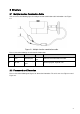
2 Structure 2.1 Multiple-function Combination Cable You can refer to the following figure for multiple-function combination cable information. See Figure 2-1. Figure 2-1 Multiple-function combination cable Please refer to the following sheet for detailed information. SN Port Name Function Connection Note 1. LAN Network port Ethernet port Connect to standard Ethernet cable. 2 DC12V Power port / Power input port. Input DC 12V. input 2.
Figure 2-2 Dimension illustration 1 Figure 2-3 Dimension illustration 2 5
3 Device Installation Important The installation wall shall min sustain 3X weight of the bracket and camera. Please follow the steps listed below to install the device. Please refer to Figure 3-1 and Figure 3-2 for reference. Step 1 Paste the installation map on the surface of the wall or the ceiling. Step 2 Dig the installation holes according to the installation map. Figure 3-1 Device installation 1 Step 3 Open the accessories bag and then take the expansion bolt out.
Figure 3-2 Device installation 2 7
4 Quick Configuration Tool 4.1 Overview Quick configuration tool can search current IP address, modify IP address. At the same time, you can use it to upgrade the device. Please note the tool only applies to the IP addresses in the same segment. 4.2 Operation Double click the “ConfigTools.exe” icon, you can see an interface is shown as in Figure 4-1. In the device list interface, you can view device IP address, port number, subnet mask, default gateway, MAC address and etc.
In the configuration tool search interface (Figure 4-1), please select a device IP address and then double click it to open the login interface. Or you can select an IP address and then click the Login button to go to the login interface. See Figure 4-3. In Figure 4-3, you can view device IP address, user name, password and port. Please modify the corresponding information to login. Please note the port information here shall be identical with the port value you set in TCP port in Web Network interface.
5 Web Operation This series network camera products support the Web access and management via PC. Web includes several modules: Monitor channel preview, system configuration, alarm and etc. 5.1 Network Connection Please follow the steps listed below for network connection. Make sure the network camera has connected to the network properly. Please set the IP address, subnet mask and gateway of the PC and the network camera respectively. Network camera default IP address is 192.168.1.108.
Figure 5- 2 Web login If it is your first time to log in, system pops up warning information to ask you whether install web plugin or not after you logged in for one minute. For detailed plug-in installation, please refer to the Web Operation Manual included in the resource CD. After you logged in, you can see the main window. See Figure 5- 3.
Please refer to the Web Operation Manual included in the resource CD for detailed operation instruction.
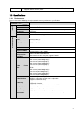
6 FAQ Bug I can not boot up the device or operate properly. Please click RESET button for at least five seconds to restore factory default setup. The water leakage occurred. The unauthorized front or rear cap remove many result in water leakage. The glass front cap has sustained heavy push or strike. The waterproof plug of the rear cap becomes loosen. IR video is poor. Do not use the proper supplying power. The IR light can not turn on completely.
Appendix Toxic or Hazardous Materials or Elements Toxic or Hazardous Materials or Elements Component Name Pb Hg Cd Cr VI PBB PBDE Circuit Board Component ○ ○ ○ ○ ○ ○ Device Case ○ ○ ○ ○ ○ ○ Wire and Cable ○ ○ ○ ○ ○ ○ Packing Components Accessories ○ ○ ○ ○ ○ ○ ○ ○ ○ ○ ○ ○ O: Indicates that the concentration of the hazardous substance in all homogeneous materials in the parts is below the relevant threshold of the SJ/T11363-2006 standard.