IR Waterproof Fixed IPC User’s Manual V1.0.
Table of Contents 1 General Introduction .............................................................................................................. 6 1.1 Overview ................................................................................................................... 6 1.2 Features .................................................................................................................... 6 1.3 Specifications ......................................................................
6 FAQ .......................................................................................................................................
Welcome Thank you for purchasing our IR waterproof fixed IP camera! This user‟s manual is designed to be a reference tool for your system.
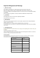
Important Safeguards and Warnings 1.Electrical safety All installation and operation here should conform to your local electrical safety codes. Before you replace the SD card, please unplug the power cable and then remove the shell We assume no liability or responsibility for all the fires or electrical shock caused by improper handling or installation. We are not liable for any problems caused by unauthorized modification or attempted repair.
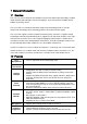
1 General Introduction 1.1 Overview This series IP camera integrates the traditional camera and network video technology. It adopts audio and video data collection, transmission together. It can connect to the network directly without any auxiliary device. This series IPC uses standard H.264 video compression technology and G.711a audio compression technology, which maximally guarantee the audio and video quality. This series IPC supports real-time monitor and listening at the same time.
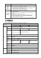
Power PoE (For -P series product only) External power adapter DC12V This function is for -P series product only. Support Power over Ethernet (PoE). Conform to the IEEE802.3af standard. Connect the device to the switcher or the router that supports the PoE function to realize the network power supply. To guarantee proper performance, please make sure the power sourcing device can supply at least 10W power.
Stream HD1(352*576/352*480) CIF(352*288/352*240) QCIF(176*144/176*128) Video Recording Speed PAL:1-ch 1f/s~25f/s adjustable NTSC:1-ch 1f/s~30f/s adjustable IR Distance 10~20M(For IR series product) Network Capacity Max support 10 network users to monitor simultaneously TCP output capacity 75Mbps UDP output capacity 85Mbps Power Consumption <7W Power DC 12V Temperature -10℃~+50℃ Working Environment Humidity 10%~90% Dimension(H*W*D) 82.7*80.2*153.5mm 1.3.
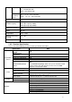
IP address filter IP address auto search function Channel Title Display Support max 6 periods. (This series product does not support this function.) After enabling manual record, no matter system is in schedule or alarm status or not, system just begins recording. System automatically enables recording function when alarm occurred. When video changes, system automatically enables record operation. There are 255 layers. O is the bottom layer and 255 is the highest layer.
RESET Support hardware reset. System needs to reboot to activate the default setup. 9-pin input and output port Port ESD protection Network port 12V power adapter 9-pin I/O Port One analog video output port One audio input port One audio output port Two alarm input port One alarm output port One network interface(RJ45 10M/100M self-adaptive Ethernet port) One red/green running status indication light.
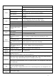
Hue:50 Watermark Record Setup Privacy Mask Enable Watermark: all Watermark type: character Watermark: DigitalCCTV Never Time title Enable. OSD transparent :128 Channel title Enable. OSD transparent :128 Channel Pre-record Time Setup Ch01 5 seconds. 0:00:00 23:59:59 Period 1:Enable motion detection/alarm Period 1: Enable motion detection/alarm Sunday COM01 General 8 1 115200 None Port 01 Disable 192.168.1.108 255.255.0.0 192.168.0.
Video Detection Alarm latch Record channel Record latch 10 seconds 1, enable 10 seconds Send email Disable PTZ activation Disable Event type: never Address: 0 Disable Motion detection Ch01, Disable 3 Period: Start time 0:00:00 End time:23:59:59 Period 1:enable Week: Sunday 5 seconds Disable 10 seconds Disable 10 seconds Disable Event type: Never Address: 0 Disable Disable Ch01 DH-SD1 1 115200 8 1 None Disable Disable Disable Disable Disable Disable Disable Disable Disable Disable Auto.
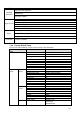
Auto maintain Auto Registration DNS Setup IP Filter Snapshot mode Frame rate Resolution Quality Auto reboot Auto delete old files Scheduled 1f/s D1 60% 2.00 each day Never Enable SN IP Port Device ID DNS Disable 1 0.0.0.0 7000 Dahua 202.101.172.35 Alternative DNS 202.101.172.
2 Structure 2.1 Device Ports This series product structure is shown as in Figure 2-1. Figure 2-1 Please refer to the following sheet for detailed information. Port Port Name Function Port 1 IR light Send out the IR compensation light to enhance the night vision effect. Port 2 / Device lens. Port 3 Photosensitive resistance It is to enable/disable the IR light according to the environment light illumination. 2.
Figure 2-2 Figure 2-3 Figure 2-4 15
2.3 Multiple-function Composite Cable You can refer to the following figure for multiple-function composite cable information. See Figure 2-5. Figure 2-5 Please refer to the following sheet for detailed information. Port Name Function Connection Note VIDEO OUT Video port output BNC Output analog video signal. It can connect to the TV monitor to view the video. AUDIO IN Audio port input RCA Input audio signal. It can receive the analog audio signal from the pickup.
Port Name Cable Color Name Note Alarm output port. It is to output the alarm signal to the alarm device. White ALARM_NO NO: normal open alarm output port. It works with the ALARM_COM port. It is to restore factory default setup. Blue RESET Orange GND When the device is working properly, please connect the blue cable (restore default setup port) to the orange cable (GND signal) for 5 seconds, the device can resume factory default setup. Ground port 2.4 Bidirectional talk 2.4.
2.5 Alarm Setup The alarm interface is shown as in Figure 2-7. Please follow the steps listed below for local alarm input and output connection. 1) Connect the alarm input device to the alarm input port (grey or brown pin of I/O port cable). 2) Connect the alarm output device to the alarm output port (White-pin) and alarm output public port (Red-pin). The alarm output port supports NO (normal open) alarm device only. 3) Open the Web, go to the Figure 2-7.
3 Installation 3.1 Bracket Installation Please follow the steps listed below to install the bracket. Please refer to Figure 3-1 for reference. Please line up the installation holes of the bottom of the device to the installation holes in the front part of the bracket. Then insert the screws to the holes to fasten the device on the bracket. Dig four holes in the wall or the surface, and then input the expansion bolts to the holes and secure.
Please use the inner hexagon wrench to turn counter clockwise to remove the front cap. See Figure 3-2. Figure 3-2 Step 2 Turn counter clockwise to loosen the front cover of the camera. Finally you can remove it. See Figure 3-3. Figure 3-3 Step 3 Use the general screwdriver to remove the four fixed screws in the connection board and then put the connection board, CCD board module aside. See Figure 3-4.
Figure 3-4 Step 4 Follow the proper direction; insert the Micro SD card to the SD card socket. See Figure 3-5.
After Micro SD card installation, put the connection board, CCD board module to the device. Put the screw holes of the connection board to the four holes of the chassis, insert the screw and then fix firmly to secure the connection board. Step 6 Turn the front cover clockwise to put it back to the device and secure firmly. Then line up the screw hole of the protection cap to the screw hole of the device chassis. Insert the inner hex screw to the holes and fix firmly to fasten the front cap in the device.
4 Quick Configuration Tool 4.1 Overview Quick configuration tool can search current IP address, modify IP address. At the same time, you can use it to upgrade the device. Please note the tool only applies to the IP addresses in the same segment. 4.2 Operation Double click the “ConfigTools.exe”icon, you can see an interface is shown as in Figure 4-1. In the device list interface, you can view device IP address, port number, subnet mask, default gateway, MAC address and etc.
Figure 4-2 Select the “Open Device Web” item; you can go to the corresponding web login interface. See Figure 4-3. Figure 4-3 If you want to modify the device IP address without logging in the device web interface, you can go to the configuration tool main interface to set. In the configuration tool search interface (Figure 4-1), please select a device IP address and then double click it to open the login interface.
Figure 4-5 25
5 Web Operation This series IPC product support the Web access and management via PC. Web includes several modules includes monitor channel list, record search, alarm setup, system configuration, PTZ control, monitor window and etc. IP camera factory default setup: IP address: 192.168.1.108. User name: admin Password: admin 5.1 Network Connection Please follow the steps listed below for network connection. Make sure the IPC has connected to the network properly.
Figure 5-2 After installation, the interface is shown as below. See Figure 5-3. Please input your user name and password. Default factory name is admin and password is admin. Note: For security reasons, please modify your password after you first login. Figure 5-3 After you logged in, you can see the main window. See Figure 5-4.
Figure 5-4 Please refer to the Outdoor IPC Web Operation Manual V1.0 included in the resource CD for detailed operation instruction.
6 FAQ Bug I can not boot up the device. Please click RESET button for at least five seconds to restore factory default setup. SD card times Do not set the SD card as the storage media to storage the schedule record file. It may damage the SD card duration. write I can not use the disk as the storage media. When disk information is shown as hibernation or capacity is 0, please format it first (Via Web). I can not upgrade the device via network.