
Datasheet


preliminary preliminary
iC-GE100
PWM RELAY/SOLENOID DRIVER
Rev B1, Page 4/12
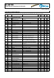
ABSOLUTE MAXIMUM RATINGS
Beyond these values damage may occur; device operation is not guaranteed.
Item Symbol Parameter Conditions Unit
No. Min. Max.
G001 V(VB) Voltage at VB -0.3 37 V
G002 I(VB) Current in VB -100 6 mA
G003 V(SW) Voltage at OUT -0.3 53 V
G004 I(SW) Output Current in OUT -6 100 mA
G005 V(DIAG) Voltage at LED -0.3 37 V
G006 I(DIAG) Current in LED -6 8 mA
G007 V(IACT) Voltage at ISET -0.3 7 V
G008 I(IACT) Current in ISET -6 6 mA
G009 V(IHOLD) Voltage at IHOLD -0.3 7 V
G010 I(IHOLD) Current in IHOLd -6 6 mA
G011 V(EN) Voltage at IN -0.3 37 V
G012 I(EN) Current in IN -6 6 mA
G013 V(SYNC) Voltage at SYNC -6 37 V
G014 I(SYNC) Current in SYNC -6 6 mA
G015 VD() Susceptibility to ESD at all pins HBM 100 pf discharged through 1.5 kΩ 2 kV
G016 Tj Junction Temperature -40 150 °C
G017 Ts Storage Temperature -40 150 °C
THERMAL DATA
Operating Conditions: VB = 10...36 V, LSW = 0.01...10 H, RACT = 6.2 k...62 kΩ, RHOLD = 6.2 k...62 kΩ
Item Symbol Parameter Conditions Unit
No. Min. Typ. Max.
T01 Ta
Operating Ambient Temperature Range
-40 85 °C
T02 Rthja Thermal Resistance Chip/Ambient surface mounted, thermal pad soldered to ca.
2 cm
2
heat sink
30 40 K/W
All voltages are referenced to ground unless otherwise stated.
All currents owing into the device pins are positive; all currents owing out of the device pins are negative.