ar y n i im prel iC-GE100 PWM RELAY/SOLENOID DRIVER Rev B1, Page 1/12 FEATURES • • • • • • • • • APPLICATIONS Current control for inductive actuators at 24 V (10 to 36 V) Power saving and power dissipation reduced switching Individual setting of energising and hold current Contact conserving switching of relays synchronous to the mains High efficient current control up to 100 mA Monitoring of coil current, supply voltage and temperature Shutdown with overtemperature and undervoltage Status indication vi
ar y n i im prel iC-GE100 PWM RELAY/SOLENOID DRIVER Rev B1, Page 2/12 DESCRIPTION iC-GE100 is a PWM driver for inductive loads, such as relay coils, solenoid valves and other inductive loads. The setpoints for the coil’s energising and hold current are pre-set by means of external resistors RACT and RHOLD. These currents can be set in a range from 10 to 100 mA. The iC-GE100 switches from energising to hold mode after 50 ms provided that the set energising current has been reached.
iC-GE100 PWM RELAY/SOLENOID DRIVER ar y n i im prel Rev B1, Page 3/12 PACKAGE DIMENSIONS DFN8-3x3 All dimensions given in mm. RECOMMENDED PCB-FOOTPRINT 2.40 5 17 R0. 0.65 0.35 2.95 0.70 0.90 1.65 SIDE BOTTOM TOP 3 0.65 0.27 0.40 3 1.70 2.
iC-GE100 PWM RELAY/SOLENOID DRIVER ar y n i im prel Rev B1, Page 4/12 ABSOLUTE MAXIMUM RATINGS Beyond these values damage may occur; device operation is not guaranteed. Item No. Symbol Parameter Conditions Unit Min. Max. G001 V(VB) Voltage at VB -0.3 37 V G002 I(VB) Current in VB -100 6 mA G003 V(SW) Voltage at OUT -0.3 53 V G004 I(SW) Output Current in OUT -6 100 mA G005 V(DIAG) Voltage at LED -0.
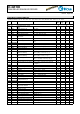
iC-GE100 PWM RELAY/SOLENOID DRIVER ar y n i im prel Rev B1, Page 5/12 ELECTRICAL CHARACTERISTICS Operating Conditions: VB = 10...36 V, LSW = 0.01...10 H, RACT = 6.2 k...62 kΩ, RHOLD = 6.2 k...62 kΩ, Tj = -40...125 °C. Item No. Symbol Parameter Conditions Unit Min. Typ. Max. Total Device 001 VB Permissible Supply Voltage Range 10 36 002 I(VB) Supply Current in VB EN < 0.8 V 20 µA 003 I(VB) Supply Current in VB EN = hi 0.
iC-GE100 PWM RELAY/SOLENOID DRIVER ar y n i im prel Rev B1, Page 6/12 ELECTRICAL CHARACTERISTICS Operating Conditions: VB = 10...36 V, LSW = 0.01...10 H, RACT = 6.2 k...62 kΩ, RHOLD = 6.2 k...62 kΩ, Tj = -40...125 °C. Item No. Symbol Parameter Conditions Unit Min. Typ. Max. 1.21 1.27 1.33 V Reference IACT and IHOLD 701 V() Reference Voltage IACT and IHOLD 702 Isc() Short-Circuit Current V(IHOLD) = 0 V or V(IACT) = 0 V -3.5 -1.8 -0.
iC-GE100 PWM RELAY/SOLENOID DRIVER ar y n i im prel Rev B1, Page 7/12 ELECTRICAL CHARACTERISTICS: Diagrams Figure 1: Operation modes: energise mode, hold mode and turn-off tmag ≈ I(SW )act × LSW VB (1) tdmag ≈ I(SW )hold × LSW Vc (SW − VB)off (2)
ar y n i im prel iC-GE100 PWM RELAY/SOLENOID DRIVER Rev B1, Page 8/12 APPLICATIONS INFORMATION Setting the coil current The following equations can be given for the energise and hold modes of the PWM control using Electrical Characteristics Nos. 703 resp. 704: RACT = RHOLD = K1 I(SW )act (3) K2 I(SW )hold (4) Example For a relay with a starting current of 70 mA and 40 mA hold current the following applies: RACT = RHOLD = 620ΩA = 8.8 kΩ 0.07 A (5) 620ΩA = 15.5 kΩ 0.
ar y n i im prel iC-GE100 PWM RELAY/SOLENOID DRIVER Rev B1, Page 9/12 10..36V LED 10..36V DIAG VB SYNC CVB 100nF LED iC-GE100 DIAG SW EN VB SYNC IACT RACT 6.2k IHOLD GND CVB 100nF RHOLD 62k iC-GE100 SW EN IACT RACT 6.2k IHOLD GND RHOLD 62k GND GND Figure 5: High-side driver for relays with free-wheeling diode Figure 6: Low-side driver for relays with free-wheeling diode CSN 10P ACN CSP 10P 10..
iC-GE100 PWM RELAY/SOLENOID DRIVER ar y n i im prel Rev B1, Page 10/12 EVALUATION BOARD iC-GE100 comes with an evaluation board for test purpose. Figures 9 and 10 show both the schematic and the component side of the evaluation board.
iC-GE100 PWM RELAY/SOLENOID DRIVER ar y n i im prel Rev B1, Page 11/12 Figure 10: Evaluation board (component side) REVISION HISTORY Rel. Rel. Date∗ B1 2015-12-03 ELECTRICAL CHARACTERISTICS Chapter Modification Page 007 deleted; double entry 101, 201, 203, 204, 406, 701, 702, 703, 704, S01, S02 synchronised with ATE 5, 6 iC-Haus expressly reserves the right to change its products and/or specifications.
iC-GE100 PWM RELAY/SOLENOID DRIVER ar y n i im prel Rev B1, Page 12/12 ORDERING INFORMATION Type Package Order Designation iC-GE100 DFN8 3 mm x 3 mm Evaluation Board iC-GE100 DFN8-3x3 iC-GE100 EVAL GE2D Please send your purchase orders to our order handling team: Fax: +49 (0) 61 35 - 92 92 - 692 E-Mail: dispo@ichaus.com For technical support, information about prices and terms of delivery please contact: iC-Haus GmbH Am Kuemmerling 18 D-55294 Bodenheim GERMANY Tel.