
Tus neeg siv phau ntawv

6
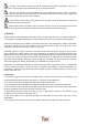
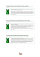
3.2 Joining process for fast coupling
3.2.1 The PTFE pipe end can be inserted into the fast coupling.
3.2.2 When the PTFE pipe need to be pulled out, Press down the clamp ring of the fast coupling with
left hand. At the same time, grasp tightly the PTFE pipe end with right hand and pull it out in an
upright manner. Attention: Be sure not to pull the bellows in a rude manner.
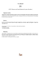
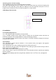
3.3 Reading of the flowmeter
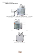
4. Installation
4.1 Installation Requirements
4.1.1. The instrument shall be installed in a level position.
4.1.2. A reliable AC220V power supply shall be located near the Exhaust System and shall be
preferably equipped with an independent air switch and leakage protector.
4.1.3. The Exhaust System shall be located where there is favorable ventilation, though, the waste gas
is harmless after disposal.
4.2 Installation
4.2.1. The Exhaust System shall be installed in a level position nearby the digestor and digestion
waste discharge system.
4.2.2. Connect the power cord for Exhaust System and switch on the power.
4.2.3. Connect the waste gas outlet of the digestion waste discharge system and the waste gas inlet of
Exhaust System to the PTFE bellows.
4.2.4. Switch on the Exhaust System, pump start working.
4.2.5. Turn the knob on the front and bottom side of the instrument until the required gas pumping
speed is reached.
(The normal gas pumping speed may be generally selected to be 1.2 m
3
/h for every 20 digestion
samples.)
Center of the taper pipe
Reading position