
MultiStorage Device Installation and Service Guide
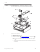
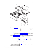
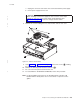

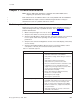
Table Of Contents
- Contents
- Figures
- About this guide
- Summary of changes
- Chapter 1. Introduction
- Chapter 2. Disassembling the 4810/4910 SurePOS 300
- Chapter 3. Problem determination
- Chapter 4. Parts catalog
- Appendix A. Input/output device commands
- Character display (VFD) commands
- Emulation mode select (00)
- Character set select (02)
- User character definition (03)
- Brightness control (04)
- Alphanumeric message scroll (05)
- Backspace (08)
- Horizontal tab (09)
- Line feed (0A)
- Carriage return (0D)
- Test (0F)
- Display position (10)
- Normal-display control mode (11)
- Vertical-scroll display control mode (12)
- Cursor on (13)
- Cursor off (14)
- Reset (1F)
- Null VFD Commands
- Emulation mode select (00)
- APA commands
- Character display (VFD) commands
- Appendix B. Notices
- Appendix C. Safety information
- Index
- Readers’ Comments — We'd Like to Hear from You
a. Unplug the connector and remove the screws that hold the power supply.
b. Lift the power supply from the unit.
Attention
When installing a new power supply, be sure to set the correct input
voltage for your area or the power supply will be damaged. See
Figure 1-3 on page 1-4 to locate the voltage selection switch.
8. Remove the screws holding the riser card and then remove riser card.
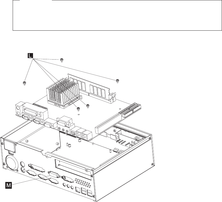
9. Using Figure 2-3 or Figure 2-1 on page 2-1, remove the screws (L) holding
the planar board to the frame.
10. Remove the RS-232 panel-mounted connector (M).
11. You can now lift the planar board from the unit.
12. To reassemble the 4810/4910 SurePOS 300, reverse this procedure.
Note:
For disassembling instructions for the SureMark printer and other I/O
bundled with the 4910, please refer to each device’s respective service
guides.
Figure 2-3. Planar board assembly
11-9-2005
Chapter 2. Disassembling the 4810/4910 SurePOS 300 2-3
|
|
|
|
|
|
|
|
|
|