
MultiStorage Device Installation and Service Guide
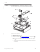
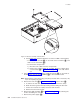
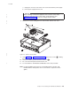

Table Of Contents
- Contents
- Figures
- About this guide
- Summary of changes
- Chapter 1. Introduction
- Chapter 2. Disassembling the 4810/4910 SurePOS 300
- Chapter 3. Problem determination
- Chapter 4. Parts catalog
- Appendix A. Input/output device commands
- Character display (VFD) commands
- Emulation mode select (00)
- Character set select (02)
- User character definition (03)
- Brightness control (04)
- Alphanumeric message scroll (05)
- Backspace (08)
- Horizontal tab (09)
- Line feed (0A)
- Carriage return (0D)
- Test (0F)
- Display position (10)
- Normal-display control mode (11)
- Vertical-scroll display control mode (12)
- Cursor on (13)
- Cursor off (14)
- Reset (1F)
- Null VFD Commands
- Emulation mode select (00)
- APA commands
- Character display (VFD) commands
- Appendix B. Notices
- Appendix C. Safety information
- Index
- Readers’ Comments — We'd Like to Hear from You
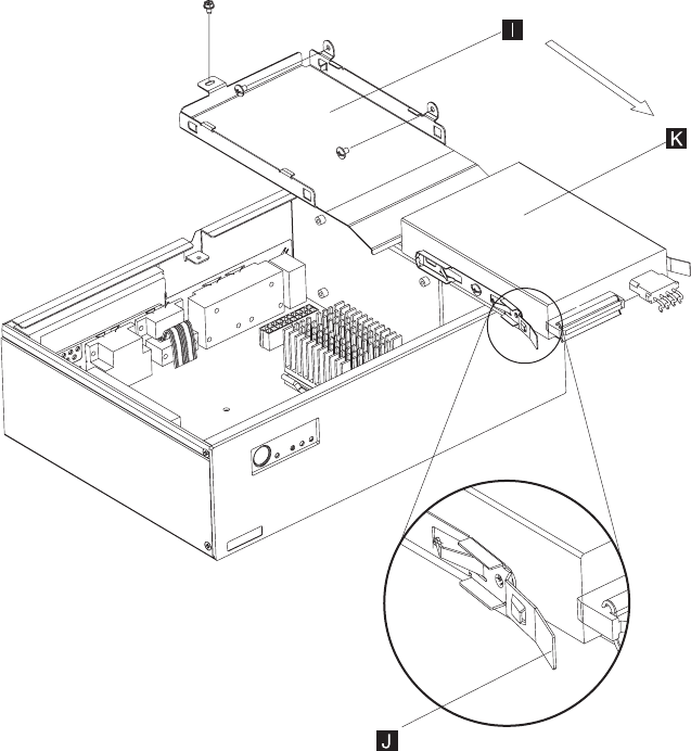
b. Using Figure 2-2, follow the directions for either an HDD or flash memory.
v Press to release the tabs (J) on each side of the hard drive (K) and
slide it out of the bracket (I).
v To remove the compact flash:
1) Disconnect the cables from the compact flash
2) Remove the screws holding the assembly. Slide the compact flash
card assembly (B in Figure 2-1 on page 2-1 ) to one side and lift
out.
4. Using Figure 2-1 on page 2-1, press and lift the clamps (G) on each side of
the dual inline memory module (DIMM) (H) to lift it from the socket.
Note: Removing the central processing unit (CPU) and heat sink is necessary only
if you are replacing the CPU.
5. Remove the heat sink (C in Figure 2-1 on page 2-1) and the CPU (D):
a. To remove the heat sink, press down and then forward on the clamp.
b. Break the silicon grease bond by twisting and then lifting the heat sink.
c. Lift the zero insertion force (ZIF) connector from the CPU.
d. Remove the CPU from the unit.
6. Remove the LED assembly (F in Figure 2-1 on page 2-1) by removing the
screws and sliding it to one side.
7. Remove the power supply (E):
Figure 2-2. Bracket assembly and hard drive
11-9-2005
2-2 SurePOS Installation and Service