MODEL 6300 VISIBLE RANGE SPECTROPHOTOMETER OPERATING MANUAL 630 026
SAFETY Please read this information carefully prior to installing or using this equipment. 1. The unit described in this manual is designed to be operated only by trained personnel. Any adjustments, maintenance and repair must be carried out as defined in this manual, by a person qualified to be aware of the hazards involved. 2. It is essential that both operating and service personnel employ a safe system of work, in addition to the detailed instructions specified in this manual. 3.
6300 SPECTROPHOTOMETER OPERATING MANUAL CONTENTS SECTION 1 INTRODUCTION Instrument Description Instrument Specification SECTION 2 INSTALLATION Unpacking Installation Displays Controls Outputs SECTION 3 4.1 4.2 OPTIONAL ACCESSORIES Optional Accessories Spares SECTION 6 3.1 3.2 3.3 MAINTENANCE General Light Source Replacement SECTION 5 2.1 2.2 2.3 2.4 2.5 OPERATION Initial Set-Up Sample Measurement Good Practice Guidelines SECTION 4 1.1 1.2 5.1 5.2 INTERFACING Analogue RS232 6.1 6.
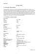
SECTION 1 INTRODUCTION 1.1 INSTRUMENT DESCRIPTION The Model 6300 is a microprocessor controlled Visible Range Spectrophotometer covering the wavelength range of 320 to 950nm with a 10nm bandwidth. The monochromator is of a modified Czerny Turner design, incorporating a stepper motor driven 1200 lines/mm holographic diffraction grating and featuring automatic second order response suppression. The 6300 has full interfacing capability for Analogue output and serial (RS232) interfacing.
SECTION 2 INSTALLATION 2.1 UNPACKING Remove the Model 6300 from the packaging and ensure the following items are present: 1. Model 6300 Spectrophotometer 2. Mains Cable 3. Pack 100 disposable Cuvettes (060 084) 4. Optional Accessories (as ordered) Any shortages or damage should be reported immediately to the Manufacturer or your local Distributor. 2.2 INSTALLATION MAINS SUPPLY The 6300 is designed to operate on 115/230V a.c. supplies (-20%+10%) 50/60Hz.
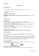
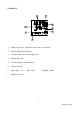
2.3 DISPLAYS 1. Primary display area - Transmission, Absorbance, Concentration 2. Primary display adjust annunciator 3. Secondary display area - Wavelength, Factor 4. Primary display units 5. Secondary display adjust annunciator 6. Operation with PC 7. Menu options - %T 8.
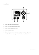
2.4 CONTROLS 1. used to adjust values on the selected display 2. used to move horizontally between menu options 3. used to select the displayed menu option 4. initiates a calibration routine 5. Print key. Provides a printout of the current reading with an incremental sample number. When pressed for the first time after a calibration the print out will give calibration information. The incremental sample number will be reset after a calibration.
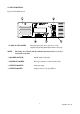
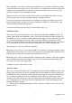
2.5 INPUTS/OUTPUTS Fig. 2.5.1 Rear Panel Layout 1. LAMP ACCESS PANEL NOTE: This panel allows the user to gain access to the tungsten halogen lamp when replacement is necessary. The Lamp Access Panel and all ventilation slots must not be covered or obstructed at any time. 2. ROCKER SWITCH On/Off switch for the unit. 3. POWER IN SOCKET IEC type connection socket for mains cable. 4. OUTPUT SOCKETS Analogue output. 5. OUTPUT SOCKET Output socket for (25 way) RS232.
SECTION 3 OPERATION 3.1 INITIAL SET-UP NOTE: If the unit is in continuous use it is recommended that it should be left switched on to obtain maximum lamp life. Do not open the sample chamber door during initialisation. Connect the unit to the correct mains supply and switch on. After switch on, the Model 6300 automatically re-aligns the monochromator at zero order wavelength. During this initialisation, the 6300 displays CAL on the primary display and the wavelength on the secondary display.
The complimentary colour method of selecting wavelength may not be applicable in all situations, perhaps because the solution has no distinct colour, or the solution is of a complex nature and the absorbing species of interest is not the predominant colour. In these circumstances it will be necessary to scan across the spectrum to determine points of maximum absorbance. Situations also exist where solutions will absorb at more than one wavelength.
Concentration Mode This mode is selected by moving the cursor to the CONC menu option using the LEFT or RIGHT arrow keys. The primary display will show the concentration, with ppm, mgl-1, gl-1, M, % or blank units. The wavelength can be adjusted using the UP and DOWN arrow keys.
3.3 GOOD PRACTICE GUIDELINES 1. For optimum performance a calibration routine should be carried out at the beginning and end of every sample batch. 2. To ensure accurate results are obtained the sample area lid should be kept in the closed position during measurement. 3. The styrene cuvettes supplied with the unit are disposable (i.e; ideally they should be used once and then thrown away).
SECTION 4 MAINTENANCE 4.1 GENERAL The 6300 has been designed to give optimum performance with minimum maintenance. It is only necessary to keep the external surfaces clean and free from dust. The sample area should always be kept clean and any accidental spillage should be wiped away immediately. To give added protection when not in use, the unit should be disconnected from the mains supply and covered with the optional dust cover (630 028).
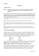
Fig. 4.2.1 Lamp Fitting 6. Close the lamp access panel and re-tighten the thumbscrew. NOTE: It is essential that only the specified replacement lamp should be used. Accuracy of optical alignment and performance cannot be guaranteed using alternative manufactured lamps. SECTION 5 OPTIONAL ACCESSORIES 5.
SECTION 6 INTERFACING Serial Interface The Model 6300 has a bi-directional RS232 interface set to: 1200 baud 7 data bits odd parity 1 stop bit The 25 way D connector allows a standard one-to-one interconnection lead to be used, as supplied with the 40 column printer. A printout is initiated by pressing the PRINT key. If the sample munber is unity, then the printout will include a header block. The sample number is incremented every time the PRINT key is pressed.
ASCII Fxxxx.x Sets the concentration factor to xxxx.x. For example: F1000 will set the factor to 1000. Note is an ASCII carriage return character. The last three commands provide an output which can readily be incorporated into most spreadsheet software packages. 6.2 RS232 Output The bi-directional RS232 interface is available on the rear panel 25 way D type connector.
EC Declaration of Conformity Jenway Model 6300 Spectrophotometer complies with the following European Standards: EN 50081-1:1992 Electromagnetic compatibility - Generic emission standard EN 50082-1:1992 Electromagnetic compatibility - Generic immunity standard (Performance criterion B) EN 61010-1:1993 Safety requirements for electrical equipment for measurement, control and laboratory use Following the provision of: EMC Directive - 89/336/EEC and Low Voltage Directive - 73/23/EEC Martyn J.