ERserver iSeries Service Functions Version 5 SY44-5902-05
ERserver iSeries Service Functions Version 5 SY44-5902-05
Note Before using this information and the product it supports, be sure to read the information in “Safety and Environmental Notices” on page vii and Appendix B, “Notices” on page 321. Sixth Edition (August 2002) This edition applies to version 5, release 2, modification 0 of Service Functions manual (SY44–5902–05) and to all subsequent releases and modifications until otherwise indicated in new editions. This edition applies only to reduced instruction set computer (RISC) systems.
Contents Safety and Environmental Notices . . . vii Chapter 2. Hardware Service Manager Danger Notices . . . . . . . . . . . . . vii Product Recycling and Disposal . . . . . . . viii Battery Return Program . . . . . . . . . . viii Environmental Design . . . . . . . . . . viii Caution Notices . . . . . . . . . . . . viii Attention Notices . . . . . . . . . . . . ix Laser Safety Information . . . . . . . . . . x Laser Safety Information (for IBM Fiber Optic Link Products). . . . . . . . . . . . .
Recovering from Product Activity Log errors while in DST . . . . . . . . . . . . Paging environment . . . . . . . . . . . Options and function keys . . . . . . . . . Analyze log . . . . . . . . . . . . . Display or print by log ID . . . . . . . . Change Product Activity Log sizes . . . . . Work with removable media lifetime statistics Display or print removable media session statistics . . . . . . . . . . . . . . Sort by ... function. . . . . . . . . . . Address information function . . . . . . .
General system and Unit Reference Code (URC) information . . . . . . . . . . . . . SPCN informational concurrent maintenance SRCs . . . . . . . . . . . . . . . IPL status SRCs . . . . . . . . . . . General status SRCs . . . . . . . . . . 196 201 201 214 Chapter 7. Initial Program Load (IPL) Information . . . . . . . . . . . . 217 IPL type, mode, and speed options . . . . IPL speed recommendations . . . . . Methods to perform IPL . . . . . . . . Alternate installation IPL . . . . . . . IPL sequence . . . .
Determining whether main storage dump data was written to disk . . . . . . . . . . Reporting the error . . . . . . . . . . Additional help . . . . . . . . . . . Performing an IOP storage dump to disk (Models 150, 170, 250, 4xx, 50x, 51x, 530, 53S, 6xx, 7xx, SB1, S20, S30, and S40) . . . . . . . . . . . . Performing a service processor storage dump (Models 270, 8xx, SB2, SB3, and 890) . . . . . Copying the IOP storage dump to removable media (All Models) . . . . . . . . . . .
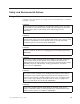
Safety and Environmental Notices Danger Notices A danger notice calls attention to a situation that is potentially lethal or extremely hazardous to people. DANGER To prevent power from switching on automatically during service procedures, select manual or secure mode on the system unit control panel or disconnect the cables that connect to J15 and J16 on the frame being serviced.
DANGER To prevent a possible electrical shock from touching two surfaces with different electrical grounds, use one hand, when possible, to connect or disconnect signal cables. (RSFTD004) DANGER To prevent a possible electrical shock, do not use the port tester during electrical storms. (RSFTD006) Product Recycling and Disposal Components of the system, such as structural parts and circuit cards, can be recycled where recycling facilities exist.
CAUTION: The battery is a lead-acid battery. To avoid possible explosion, do not burn. Exchange only with the IBM-approved part. Recycle or discard the battery as instructed by local regulations. In the United States, IBM has a process for the collection of this battery. For information, call 1-800-426-4333. Have the IBM part number for the battery unit available when you call. (RSFTC225) CAUTION: The circuit card contains lead solder. To avoid the release of lead (Pb) into the environment, do not burn.
Laser Safety Information Laser Safety Information (for IBM Fiber Optic Link Products) CAUTION: This system may contain laser products called the IBM Optical Link Module (OLM), Serial Optical Converter (SOC), or Optical Link Card (OLC). In the United States, these fiber optic links are certified by IBM as Class I laser products that conform to the requirements contained in the Department of Health and Human Services (DHHS) regulation 21 CFR Subchapter J.
About Service Functions (SY44-5902-03) This book provides basic information about iSeries functions that are commonly used by field hardware service representatives. It provides enough detail for the hardware service representative to gather information about hardware problems while under the direction of the next level of support. The book is meant to assist the hardware service representative in gathering information about commonly encountered field problems.
v The iSeries Setup and Operations CD-ROM. This CD-ROM contains IBM iSeries Access for Windows and the EZ-Setup wizard. iSeries Access for Windows offers a powerful set of client and server capabilities for connecting PCs to iSeries servers. The EZ-Setup wizard automates many of the iSeries setup tasks. iSeries Navigator IBM iSeries Navigator is a powerful graphical interface for managing your iSeries and AS/400e servers.
Chapter 1. Dedicated Service Tools (DST) Introduction . . . . . . . . . . . . . . 1 Dedicated Service Tools requirements . . . . . 1 System paging environments . . . . . . . . . 2 Stand-alone paging (non-paging) . . . . . . 2 Limited paging . . . . . . . . . . . . 2 Full paging . . . . . . . . . . . . . . 3 Accessing Dedicated Service Tools . . . . . . . 4 Performing an IPL to DST . . . . . . . . . 4 Changing a service tools user ID. . . . . . . 5 Resetting QSECOFR service tools user ID . . . .
v One workstation for each system partition. v A valid service tools user ID and password to sign on to DST. IBM supplies service tools user IDs that have different levels of privileges. See “Work with service tools user IDs” on page 25 for more information. To make a printout, attach the printer to the workstation I/O processor or storage media unit that is performing the service function.
Attention: For systems with multiple logical partitions, performing an IPL on the primary partition causes the secondary partitions to be powered down. Failing to power down these secondary partitions will cause an abnormal power-down on the secondary partitions and possible loss of data.
The following options are available in the full paging environment for all operating systems: v Perform an IPL v Install the operating system v Work with Licensed Internal Code v Work with disk units v v v v v v Work with DST environment Start a service tool Work with remote service support Work with system partitions Work with system capacity Work with system security Note: The following options are operating system-dependent.
1. Select a type B IPL in Manual mode. For information on how to select IPL options, see “IPL type, mode, and speed options” on page 217. Attention: For systems with logical partitions, performing an IPL on the primary partition causes the secondary partitions to be powered down. Failing to power down these secondary partitions will cause an abnormal power-down on the secondary partitions and possible loss of data. 2.
Resetting QSECOFR service tools user ID Methods to recover from a disabled QSECOFR service tools user ID: v Sign on with the QSECOFR OS/400 user profile. v Use the XPF CL command CHGDSTPWD with *DEFAULT as the parameter value. Executing this command will enable the profile (if disabled), reset the profile’s password to QSECOFR, and set the password to expired. After using the CHGDSTPWD command, you can change the password of the QSECOFR service tools user ID by signing on to DST.
Pressing the System Request Key while the system is operational If your system has the OS/400 operating system, you can access DST by using the following procedure only when the system is in debug mode. Debug mode is an environment to test programs. It allows you to select a function key and access DST during the IPL process (see “Perform an IPL” on page 11). For more information on debug mode, see iSeries Licensed Internal Code Diagnostic Aids Volume 1 . From the console, perform the following steps: 1.
Type QSRV as the valid user ID and get the password from the customer. If the customer has changed the full DST authority user ID or password, ask the customer for the correct values. Note: If prompted for a password, be sure to give the new (changed) password to the customer. Note: V5R1 limits you to three sign on attempts to DST. After three unsuccessful attempts, the service tools user ID will be disabled. The system administrator with QSECOFR authority will need to reset the ID. 4.
d. The removable media becomes active. There is a delay while the system loads information from the load source. While running a process, the system continuously updates SRCs on the control panel that show the status. 8. Wait for the Install Licensed Internal Code display to appear on the console. The wait varies depending on the speed of the removable media unit and the processor speed for the specific system model. Notes: a.
v The F3 function key returns you to the primary menu of the service tool you are using. v The F12 function key returns you to the previous DST display. v The F16 function key returns you to the Use Dedicated Service Tools (DST) display from the service function you are in. The active service function is not canceled. To display the service function again, select the Work with DST environment option.
Table 1.
Licensed Internal Code information and PTFs, and display free space. Select this option from the Use Dedicated Service Tools (DST) display. For more information on Licensed Internal Code fixes and PTFs, see “Licensed Internal Code (LIC) introduction” on page 223 and the system operation information. Licensed Internal Code general information There can be two versions of some Licensed Internal Code modules on the load-source disk unit.
Note: There are two copies of some Licensed Internal Code on the load-source disk unit. It is the IPL type (A or B) that selects the Licensed Internal Code level with which your system will run. v Rebuild Licensed Internal Code This option allows you to rebuild the Licensed Internal Code. On RISC systems, this means combining free space for all nucleus and service Load IDs.
Options on the Work with Disk Units Display Options and menu flow for the Work with disk units options vary depending on the system paging environment (see “System paging environments” on page 2). Use the following table as a reference during problem analysis and system repair. Select the Work with disk units option on the Use Dedicated Service Tools display. Options and menu flow for this function vary depending on the paging environment. Table 2.
Table 2. Paging environments and the work with disk unit options (continued) Paging environment Limited paging Work with disk unit options 1.
Table 2. Paging environments and the work with disk unit options (continued) Paging environment Limited paging Work with disk unit options 2.
Table 2. Paging environments and the work with disk unit options (continued) Paging environment Work with disk unit options Full paging 1. Display disk configuration v Display disk configuration status v Display disk configuration capacity v Display disk configuration protection v Display non-configured units v Display device parity status v Display disk hardware status v Display disk compression status 2.
v Include unit in device parity protection This option allows you to add an unprotected disk unit to an existing parity set. v Enable remote load-source mirroring For details on this option, see the main heading “Work with ASP threshold”. v Disable remote load-source mirroring For details on this option, see the main heading “Work with ASP threshold”. v Start compression on non-configured disk units Select this option to increase the effective disk unit capacity of non-configured disk units.
Select this option to display the threshold and overflow values of the ASP and the assigned disk units. This display is also available under the Display disk configuration option (see “Display disk configuration” on page 18). v Delete user ASP Select this option to delete a user-defined ASP (ASPs 2 through 16). v Add units to ASPs Select this option to add non-configured units to an existing ASP. This increases the amount of storage that is assigned to the system ASP (ASP 1).
Work with device parity protection: Select this option to perform the system functions that handle device parity protection on the system. Device parity protection is a data redundancy feature available on some storage media units. It is maintained across all the units that are within the parity set. If one unit fails, the units within the set handle the functions for the failed unit. This type of protection can improve system availability and reduce the possibility of data loss.
This option reads the data (recorded using the Save disk unit option) from the removable medium and writes the data on the disk unit. The data can be restored to a disk unit of the same type or to a different type of disk unit that has the same or larger storage capacity. When all data is restored to the disk unit, an ending display appears with status information. If the replaced disk is load source, the system will IPL to DST from the new disk. For the others, the system will not re-IPL.
When a failed disk unit is repaired, use this option to rebuild the data. This option allows you to use the redundancy feature of device parity protection to rebuild data to a disk unit. Attention: If there are several disk unit incompatibilities, make certain that the correct units are installed. v Reclaim IOP cache storage When the IOP cache memory fails and needs to be replaced, this option allows you to remove and destroy the damaged data in the IOP cache.
– The results of the Analyze disk unit surface option (under the Work with disk unit recovery option) show which pages have data check conditions. Use the Display/change page data option to assign those sectors to new locations on the disk. – To inspect and change the 64 bytes of page header, if necessary. – To inspect and change the 4096 bytes of page data, if necessary. The Display/change page data option has the following functions: – Reading data from a selected page.
– – – – Display Enable Disable Change privileges - Revoke - Grant – Change description v System values v Service tools device IDs – Create – Reset password – Delete – – – – Display Enable Disable Change attributes - Revoke - Grant – Change description v Service tools security data – Reset operating system default password – – – – Change operating system install security Work with service tools security log Restore service tools security data Save service tools security data – Password level Work with
Type the desired option number in this field next to the active service tool name you are displaying or ending. Work with system devices Before you select an option on the Work with System Devices display, ensure the following is true: v If you have a printer available, ensure that it is connected and configured to the same I/O processor or storage media unit as the workstation.
Table 3.
v Force a prompt for system type on the next IPL v Force a prompt for system unique identifier on the next IPL (only for OS/400) Note: The Work with system values option is not available under basic or full DST authority. For more information on authority, see “Work with service tools user IDs” on page 25. Work with alternate installation device An alternate installation IPL is a special kind of type D IPL.
Service functions will not interrupt the console display unless you have already set debug mode. Sign-on is necessary to access DST. All active service functions end. v Start DST in debug mode on IPL Service functions can interrupt the normal operating system process to display debug information. When an operating display appears, you can enter DST by performing the System Request Key procedure. This displays the Use Dedicated Service Tools (DST) display without requiring you to log on to DST.
- Dump to media When the output device is a printer or media, the actual dump task runs asynchronously with the Display/Alter/Dump control functions. That is, while a dump is completing on a printer or media, you can operate the display/alter function (output device is the display), or you can make other dump requests for a printer or media. The system saves dump requests in a first-in-first-out queue and processes them one at a time.
there is no practical limit to the number of requests you can have waiting to be processed. When you exit the Licensed Internal Code Log display, all the dumps that are running end. To determine the dump status, use the Display the status of the Licensed Internal Code option. For more information, see iSeries Licensed Internal Code Diagnostic Aids - Volume 1. Licensed Internal Code (LIC) trace: Select this option from the Start a Service Tool display.
v v v v v Display or print a current main storage dump Display or print a copy of a main storage dump Copy a current main storage dump to removable media Copy a current main storage dump to the MSD library Copy a main storage dump from the MSD library to removable media v Copy a main storage dump from removable media to the MSD library An MSD library is available to access copies of main storage dumps. The contents of the library are stored in auxiliary storage.
This option allows you to do the following tasks: v Change the IPL attributes v Set the IPL attributes and restart the system v Set the IPL attributes and power off the system Note: At the next IPL, a file rebuild might be necessary. For more information on a file rebuild, see the system operation information. Performance data collector: Select this option from the Start a Service Tool display. This option allows you to gather detailed information about system performance.
Options and Function Keys The Work with Communications Traces display has the following options and function keys: v Start trace (F6) This function key allows you to start tracing the data on a communications configuration object. The Start Trace display appears after you press this function key. For more information, see “Starting a trace” on page 34. v Stop trace (option 2) This option appears only on the Work with Communications Traces display. It allows you to end the trace and stop collecting data.
Work with Communications Traces Type choice, press Enter. 2=Stop trace 4=Delete trace 7=Display message 8=Restart trace Configuration Opt Object _ LosAngeles _ Mpls _ Tucson 6=Format and print trace Type Trace Description Line Test LosAngeles Line NWI Test Mpls Line Test Tucson Line F3=Exit F5=Refresh F11=Display buffer size F6=Start trace F12=Cancel Protocol Trace Status SDLC Active ISDN Stopped ASYNC Waiting F10=Change size Details of the trace, including status, are displayed.
Start Trace Configuration object . . . . . . . . . _________ Type . . . . . . . . . . . . . . . . . 1 3=Network server Trace description . . . . . . . . . . 1=Line 2=Network interface ____________________ Buffer size (in kilobytes) . . . . . . 1 1=128, 2=256, 3=2M, 4=4M, 5=6M, 6=8M, 7=16M, 8=32M, 9=64M Stop on buffer full Y=Yes, N=No Data direction . . . . . . . . . N . . . . . . . . . . . 3 Number of bytes to trace Beginning bytes . . . . . . . . . . Ending bytes . . . . . . . . . . .
You can select how much data is traced in a frame of data. The value that is entered is the amount that is saved as part of the trace. The minimum value that is allowed for both the beginning and the end value is 36 bytes. Those 36-byte minimum values include the protocol header. The configuration object you are tracing determines the maximum value that is allowed. Notes: 1. The BSC protocol ignores the beginning and ending byte values. 2. The SDLC, high-level data link control (HDLC), X.
Format Trace Data Configuration object . . . . . . TRNLINE Type . . . . . . . . . . . . . . LINE Type choices, press Enter. Controller . . . . . . . . . . Data representation *ALL . . . . . 3 *ALL, name 1=ASCII, 2=EBCDIC, 3=*CALC Format RR, RNR commands . . . N Y=Yes, N=No Format Broadcast data . . . . Y Y=Yes, N=No Format MAC or SMT data only. . N Y=Yes, N=No Format UI data only . . . . . N Y=Yes, N=No Format TCP/IP data only . . .
Record Data Record Record Data Controller Number Number Poll/ Number S/R Length Status Timer Type Name/Number Command Sent Received Final ------ --- ------ -------- --------------- ------ ------------- ------- ------------- ----7 R 69 00000000 12:29:56.72963 EBCDIC ZSDLLC30 /01 XID ON Data . . . . . : 3245056150080000 0084C00000000000 01010B0000010900 00000007000E0DF4 *.../&;...D{....................4* DADBCC4BDACBCDCE EFCGC5F31017F116 1101130011F9F4F0 F6F5F0F0F1F0F1F0 *ABC.ABCDEFG..1......
Controller name/number Indicates which controller originated the frame or record. In some conditions, this data is not available, and the column remains blank. Note: The formatted trace output is not security protected. Customer passwords are shown going across the line. Communications trace limitations: Only two communications traces can run concurrently on one communications controller. Only one trace can exist for the same configuration object at the same time.
Save Licensed Internal Code This option allows you to save the Licensed Internal Code to tape, with all currently applied PTFs. You can use the tape to restore the Licensed Internal Code after a failure. Note: When your system is in the full or limited paging environment (see “System paging environments” on page 2), the appearance of the Save Licensed Internal Code option varies depending on the operating system. For more information, see Appendix A, “OS/400 Operating System” on page 281.
Through remote service support, DST functions that would normally be available only at the local system console can be accessed from a remote site. Remote service support requires the following: v An electronic customer support communications line. v The system at the local site must be IPLed to DST or past DST. v Remote service support must be enabled and activated at the local site (see “Allowing access for remote service support” and “Activating remote service support”).
Note: Releasing the line does not reset the modem mode. Remote service uses asynchronous mode. If the modem was originally set to a mode other than asynchronous, you must manually select the mode again. This ends the procedure. Note: Electronic customer support is not available while DST remote service is active. For more information on electronic customer support, see the system operation information.
with the QSYCHGDS API. When set to ’No,’ the password can only be changed from DST or by using the QSYCHGDS API with a requesting user that has the necessary authority. Chapter 1.
44 Service Functions V5R2
Chapter 2. Hardware Service Manager Introduction . . . . . . . . . . . . . Hardware Service Manager options . . . . . Packaging hardware resources . . . . . . Logical hardware resources . . . . . . . Locate resource by name . . . . . . . . Failed and non-reporting resources . . . . System Power Control Network (SPCN) . . . Battery power unit information . . . . . . Work with service action log . . . . . . Option field . . . . . . . . . . . Status field . . . . . . . . . . . Date and time fields . . . . . .
Hardware Service Manager Attention: This utility is provided for service representative use only. System unit . . . . . . . : Release . . . . . . . . . : 9406-820 10-4046M V4R5M0 (1) Select one of the following: 1. 2. 3. 4. 5. 6. 7. 8. Packaging hardware resources (systems, frames, cards,...) Logical hardware resources (buses, IOPs, controllers,...
Table 5.
Note: The Hardware contained within package option will not be valid for a remote system unit since no packages for hardware within them will be created. This is because HRI will not see VPD from any resources within a remote system unit or remote expansion unit. Packaging Hardware Resources Local system type . . . . : 9406 Local system serial number: 10-0033333 Type options, press Enter.
Packaging Hardware Resources Local system type . . . . : 9406 Local system serial number: 10-0033333 Type options, press Enter.
Logical Hardware Resources Select one of the following: 1. 2. 3. 4. System bus resources Processor resources Main storage resources High-speed link resources Selection F3=Exit F6=Print configuration F12=Cancel Figure 8. Example Logical Hardware Resources display.
Locate Resource By Resource Name Type resource name to be located, press Enter. Resource name . . . . . . . . . . F3=Exit F9=Unmapped Resource Names F12=Cancel Figure 9. Example Locate Resource By Resource Name display The system responds by displaying one of the following messages: v Resource is not found. The system displays the following message: x does not exist as a current resource name. (Where x is the resource name that the user specified.) v Resource is found but is a reserved resource name.
Logical Hardware Resources Type options, press Enter. 2=Change detail 4=Remove 5=Display detail 6=I/O Debug 7=Verify 8=Associated packaging resource(s) Resource Opt Description Type-Model Status Name _ Communications IOP 2619-001 Operational CC02 F3=Exit F5=Refresh F6=Print F9=Failed resources F10=Non-reporting resources F11=Display serial/part numbers CC02 located successfully. F12=Cancel Figure 10.
Failed and non-reporting resources The Failed and non-reporting hardware resources option appears on the Hardware Service Manager display when the system is in the full or limited paging environment. It allows you to display a list of the logical hardware resources that either failed or did not report to the system at the last IPL.
Failed and Non-Reporting Logical Hardware Resources Type options, press Enter.
System Power Control Network (SPCN) The System Power Control Network (SPCN) option appears on the Hardware Service Manager display when the system is in the full or limited paging environment. This option is not available on all systems. Problems that the SPCN reports to the operating system are logged. Select the System Power Control Network (SPCN) option to work with the network structure for SPCN. See the Service Action Log to display and work with the log information.
Figure 13 on page 55 shows examples of: v A battery power unit that is not due for replacement in the system unit v A battery power unit that is not installed in the system unit v A battery power unit that is due for replacement in the expansion unit For more information, press the Help key at the Battery Power Unit Information display.
Option field Use the Option field to perform the following functions: v Display the failing item information This option displays the possible failing items along with part action, description, location, and SRC word information. Choose the Help function key for more information about each of these fields. v Close a NEW entry After a problem has been fixed, select this option to change the status to CLOSED. This option allows you to mark service action log entries with the appropriate status of the repair.
Display label location work sheet The Display label location work sheet option appears on the Hardware Service Manager display when the system is in the full or limited paging environment. It allows you to display current configuration location information. You can also print a worksheet that shows location information by selecting the print function on the Label Location Work Sheet display. The work sheet printout contains a field in which you can enter label information.
Device Concurrent Maintenance Type the choices, then press Enter. Specify either Physical Location or Resource Name. Physical Location . . . Frame ID: Position: OR Resource Name . . . . . Device Resource Name: Specify action as 1=Remove device 2=Install device Action to be performed . . . . . . . . . : Enter a time value between 00 and 19. Time delay needed in minutes . . . . . . : 00 Serial number of frame (not needed if xxxxxxxxxx shown). Frame serial number . . . . . . . . .
Usually, the serial number information is not needed, but if the server detects a duplicate Frame ID in your Device Concurrent Maintenance request, you will be returned to this same screen with a blank serial number field. Simply put the serial number for the CEC that originally controlled the frame into this field. This serial number can be found in the Service Action Log FRU Details or in Hardware Service Manager information screens. Disk Unit Hardware Resource Information Details Type...................
Device Concurrent Maintenance Type the choices, then press Enter. Specify either Physical Location or Resource Name. >>> Physical Location . . . Frame ID: 1... Position: L01.. <<< OR Resource Name . . . . . Device Resource Name: .......... Specify action as 1=Remove device 2=Install device Action to be performed . . . . . . . . . : 1 Enter a time value between 00 and 19. Time delay needed in minutes . . . . . . : 00 Serial number of frame (not needed if xxxxxxxxxx shown). Frame serial number . . . . . . . .
You can change detailed information about a specific resource by selecting the Change detail option or function key. The information varies depending on the device selected. The following is a Change detail display for a communications IOP packaging hardware resource: Change Packaging Hardware Resource Detail Description . . . . . . . . . . . . : Communications IOP Type-Model . . . . . . . . . . . . : Serial number . . . . . . . . . . . : 2620-001 10-3157011 Type changes, press Enter. Resource name . .
Change Logical Hardware Resource Detail Description . Type-Model . Status . . . Serial number . . . . . . . . . . . . . . . . . . . . . . . . . . . . . . . . . . . . . . . . . . . . : : : : Current resource name . . . . . . . : Communications IOP 2620-001 Operational 10-3157011 CC08 Type changes, press Enter. New resource name . . . . . . . . . F3=Exit F5=Refresh F9=Display detail F12=Cancel CC08 F6=Print Figure 19.
become available again. The I/O processors and I/O adapters to which these disk units are attached may only be replaced while the domain is powered off. Any other actions on these hardware resources are unsupported and may cause failures requiring a system IPL to recover. There are no restrictions on the service actions that can be performed on other hardware resources in the power domain. v A power domain containing hardware resources that are in use by the operating system cannot be powered off.
To create the frame information, press the Create containing hardware resource function key. The following display appears and allows you to select the type of packaging hardware resource (frame) to contain the resource you selected. Select Packaging Model Type option, press Enter. 1=Select Opt _ _ _ Description Rack Enclosure Rack Enclosure Rack Enclosure F3=Exit F6=Print Type-Model 9309-002 9309-001 5044- F12=Cancel Figure 21.
The Create containing hardware resource function key is available only on the packaging hardware resources displays. To access this function from the logical displays, you must select the Associated packaging resource(s) option (see “Display associated resources” on page 67). Debug the resource From packaging displays: The I/O debug option is available only on the logical hardware resources displays.
v Take/Release ownership — If this system presently owns the resource, selecting this option will allow the system to release its ownership. If this system does not presently own the resource, selecting this option will allow the system to take ownership. For more information on I/O debug, see “Performing an IOP dump using hardware service manager (All Models)” on page 279 and the iSeries Licensed Internal Code Diagnostic Aids - Volume 1 information.
Logical Resources Associated with a Packaging Resource Packaging resource: Communications IOP Type-Model Resource Name 2620-001 P17 Type options, press Enter. 2=Change detail 4=Remove 5=Display detail 6=I/O Debug 7=Verify 8=Associated packaging resource(s) Opt _ _ _ Description Communications IOP Communications IOA Communications Port F3=Exit F5=Refresh Type-Model 2620-001 2620-001 2620-001 F6=Print Resource Name Status CC08 Operational LIN09 Operational CMN07 Operational F12=Cancel Figure 22.
Packaging Resources Associated with a Logical Resource Logical resource: Type-Model Resource Name 2620-001 CC08 Communications IOP Type options, press Enter. 2=Change detail 3=Concurrent Maintenance 4=Remove 5=Display Detail 8=Associated logical resource(s) 9=Hardware contained within package Opt Description _ Communications IOP F3=Exit F5=Refresh F10=Non-reporting resources Type-Model Frame ID Resource Name 2620-001 1 P17 F6=Print F12=Cancel F13=Unresolved locations Figure 23.
If the system detects gaps in the logical sequence, the following display appears: Display Card Gap Information Resource Type-Model Frame ID Name 9406-500 1 FR01 Description System Unit F3=Exit F5=Refresh F6=Print Card Position 2 6 7 8 F12=Cancel Figure 24. Example Display Card Gap Information display The Card Position column shows the card location that is empty. One or more card positions might be empty for a single card enclosure.
The Hardware contained within package option is available only on the Packaging Hardware Resources displays. Use this option to view the next level of hardware for the packaging hardware resources. This option functions only when a plus sign (+) appears after the description. For more information on symbols, see “Symbols on the Hardware Service Manager displays” on page 93.
The Non-reporting resources function key appears on various Logical Hardware Resource displays. It allows you to view a list of the logical resources that were detected in the past but are not being detected by the server now. A non-reporting resource indicates that one of the following occurred: v The resource might have been removed from the server. v The resource might be powered off. v There is a problem in the signal path between the server and the device. v There is a resource failure.
Logical Hardware Resources Associated with IOP Type options, press Enter.
Packaging Hardware Resource Detail Resource name . . . . . . . . . . . : Description . . . . . . . . . . . . : Type-Model . . . . . . . . Actual type-model . . . . . Serial number . . . . . . . Part number . . . . . . . . Physical location . . . . . Location text . . . . . . Frame ID . . . . . . . . EIA location . . . . . . Card position . . . . . . Device position . . . . . Manufacturing ID . . . . Actual manufacturing ID . . Shared by multiple systems Manufactured by IBM . . . .
Location text This field shows the text location information that was entered manually by the user. All packages, except stand-alone units, display the location of the frame which contains them. The stand-alone units display the text information for themselves. Frame ID This is the identifier of the frame enclosure. EIA location This field shows the Electronics Industries Association (EIA) location within the frame. The information is manually entered by the user from the change detail screen.
Manufactured by IBM This field contains a 1 if the resource was manufactured by IBM or a 2 if it was not. Shared by multiple systems This field contains a 1 if the resource is shared between multiple systems or a 2 if it is not. From logical displays: You can select the Display detail option from various logical resource displays. This option allows you to view additional information about a specific resource.
– System board – System card v Communications – I/O bus – Adapter – Port – Channel Display resources requiring attention From Hardware Service Manager display: The Display resources requiring attention function key appears on the Hardware Service Manager display. Most hardware resources automatically report information to the system, but some resources might require user input.
details” on page 61). Asterisks (*) might appear on both sides of a value that appears on the Change Packaging Hardware Resource Detail display. This shows the value that is causing the resource to need attention. Note: If no action is taken, the following information applies: v The resource does not appear on the packaging resource displays or printouts. On some resources displays you can press the Unresolved locations function key to view the unresolved locations information.
select the Display detail option (see “Display resource details” on page 73) to view the resource status. This indicates the current status of the resource as reported by the hardware. Status values: v Unknown - Cannot determine status. The resource may be non-reporting or unable to communicate status. v Operational - Resource is functioning normally. v Failed - Resource has failed and is not functional. v Errors - Card or device has detected errors but may still be functional.
The System bus resources option is available only on the Logical Hardware Resources display (see “Logical hardware resources” on page 49).
Logical Hardware Resources on System Bus System bus(es) to work with . . . . . . Subset by . . . . . . . . . . . . . . . *ALL *ALL, *SPD, *PCI, 1-511 *ALL *ALL, *STG, *WS, *CMN, *CRP Type options, press Enter.
Logical Hardware Resources on System Bus System bus(es) to work with . . . . Subset by . . . . . . . . . . . . . *ALL *ALL, *SPD, *PCI, 1-511 *ALL *ALL, *STG, *WS, *CMN, *CRP Type options, press Enter.
There are resources with unresolved locations. Press F13 to see list. Select the Unresolved locations function key to view the Hardware with Unresolved Locations display. To update or change the location information, select the Change detail option on the Hardware with Unresolved Locations display. Note: If you take no action, the following applies: v The resource does not appear on the packaging resource displays or print-outs.
page 71. Selecting this option removes this hardware resource and the associated logical or packaging resources information. Use this option after performing a hardware upgrade when hardware resources were removed. Reserve frame space From packaging displays: The Reserve frame space function key appears only on the Packaging Hardware Resources display. Select the Reserve frame space function key to access the Reserve Frame Space display.
Work With High-Speed Link (HSL) Resources Type options, press Enter.
Display HSL Information HSL loop number . . . . . . . . . : 257 HSL loop resource Type-model . . Serial number . Resource name . HSL OptiConnect . . . : 224E . . . : 10-9309001 . . . : SB02 status: Not Available Status . . . . . : Operational Part number . . . : 111222333444 Leading port to next resource . . . . . . . . . . . . . . : Link status . . . . : Operational Link type . . . : Copper Type of connection .: Internal Link type . . . : 500 Trailing port from previous resource Link status . . . .
This screen is also displayed when F7 is selected and the previous resource is a remote HSL NIC and when F8 is selected and the next resource is a remote HSL NIC. Display HSL Information HSL loop number . . . . . . . . . : 257 HSL I/O bridge resource Type-model . . . : 1999-999 Serial number . . : 21-1111111 Resource name . . : BC06 Status . . . . : Operational Part number . . : 111111111111 Leading port to next resource . . . . . . . . . . . . . . : Link status . . . . : Operational Link type . . .
Part number: This field represents the part number of the logical hardware resource. Resource name: The resource name is the symbolic name of the logical hardware resource. The resource name was either created by the system when the hardware was first sensed, or was updated to a new value by a user on a change screen. The logical hardware resource name is autonomous from the packaging hardware resource name. HSL OptiConnect Status: This field represents the status for networking.
Link type: This field shows the type of link to which this port connects. Possible values are optical or copper. Type: The port may be connected to another resource via two possible connections: internal or external. Internal The user cannot see an internal connection. It is internal to the resource. If the connection is internal, the port number field will be blank. External The user can see an external connection. The port number field will contain a value.
Resource name: The resource name is the symbolic name of the logical hardware resource. The resource name was either created by the system when the hardware was first sensed, or was updated to a new value by a user on a change screen. The logical hardware resource name is autonomous from the packaging hardware resource name. Mode: The mode field indicates whether or not the ownership of this resource can be switched to another system. The possible values are Private or Switchable.
Resource name: See “Resource name” on page 88. Port: This field shows the port number to which another resource in the loop is connected. This field is blank if the link is an internal link. Type: See “Type” on page 89. Status: The current status of the link as reported by the hardware. Possible values for the status field are: Unknown Cannot determine status. A resource may be non-reporting or unable to communicate status. Operational The link is operating normally.
When F11 Display tower information is selected from the Logical Hardware Associated With HSL Loops display, the following display appears. Logical Hardware Associated With HSL Loops Type options, press Enter.
ports, cartridge tape units, optical storage units, diskette units, and File Server adapters. For information on how to run a verification procedure, see “Verification procedures” on page 95. Symbols on the Hardware Service Manager displays The symbol field is next to the description field on several displays. The following list describes these indicators: Symbol Description + This symbol appears only under the Packaging hardware resources option.
v Resource name, type-model, serial number, and logical address 4. Legend v Descriptions of the indicators v Logical address format information 132-character width printouts consist of the following: v description v type-module v serial number v location data – frame ID – device position – card position v logical resource name v part number v logical address You can sort the printout by location or logical address data. To print the system configuration list, perform the following procedure: 1.
1. Select the Logical hardware resources option on the Hardware Service Manager display. 2. On the Logical Hardware Resources display, select one of the following options to display details: v System bus resources v Processor resources v Main storage resources v High-speed link resources 3. Use the Print function key to print the information. This ends the procedure.
2. You can test some workstations by using the Test Request function key while the operating system Sign On display is shown. 3. See the specific device information for possible off-line tests that you can run. Verify optical storage unit You can check optical storage units for correct operation by performing the verification procedure (see “Hardware Service Manager — Verify” on page 95).
For more information, see “Verification procedures” on page 95. Verify communications You can check communications for correct operation by performing the verification procedure.
98 Service Functions V5R2
Chapter 3. Product Activity Log Introduction . . . . . . . . . . . . . Product Activity Log (PAL). . . . . . . . The Service Action Log (SAL) . . . . . . Product Activity Log location . . . . . . Recovering from Product Activity Log errors while in DST . . . . . . . . . . . Paging environment . . . . . . . . . . Options and function keys . . . . . . . . Analyze log . . . . . . . . . . . . Display or print by log ID . . . . . . . Change Product Activity Log sizes . . . .
Product Activity Log (PAL) The PAL is the general use system log containing entries for informational events, thresholding incidents, dumps, and errors that need to trigger service actions. The entries are full of basic and detailed information on the event in a somewhat raw form. This option is selected from the Start a Service Tool menu. It allows you to display or print data that has been logged for various components of the system.
v Work with service action log The SAL is a utility that scans the PAL and displays entries that require service representative action. It pulls out the relevant information from those entries and formats it to the display to show service information, such as failing resource names, field replaceable unit (FRU) part numbers, and FRU locations.
The Licensed Internal Code maintains a 128KB shadow log on the load-source disk. The log contains a duplicate copy of the latest entries. When you perform an IPL to Dedicated Service Tools (DST), the Product activity log option uses this shadow log. Note: The shadow log is not available in the stand-alone environment (Type-D IPL). In the limited paging environment, some options are not available. For more information on paging environments, see “System paging environments” on page 2.
– Logical address (see “Logical address format” on page 114) – Class – Resource name Note: To gather information by using the resource name, select the Display summary option. Then select the F9 key (Sort by...) and sort by resource name. The Log Summary by Resource Name display appears and shows a summary of the resources and the number of entries (see Figure 43 on page 106). Select Analysis Report Options Type choices, press Enter. Report type . . . . 3=Print Analysis Optional entries to Informational .
Note: Events that are related use the same log ID. For example, if a workstation controller has an error that causes an automatic dump, both the permanent error and the IOP dump have the same log ID. Change Product Activity Log sizes Select this option from the Product Activity Log display. This option allows you to change log area sizes. Note: To change the size of all the logs at one time, select the Change all function.
Symbol Explanation Action >> Media replacement recommended Copy the contents to the new media and discard the old media. > Media approaching replacement criteria v Replace the media if the format is: – QIC-120 – 7208 2.3GB – 6250 bpi density v If the format is anything other than above, monitor the media. Display or print removable media session statistics Select this option from the Product Activity Log display.
Log Summary by Class From . . : 01/11/93 11:13:39 To . . : 02/22/93 11:13:39 Type options, press Enter. 5=Display 6=Print Opt Class / System Reference Code *ALL . . . . . . . . . . . . . . . . . . . Machine Check . . . . . . . . . . . . . . . B600 0219 . . . . . . . . . . . . . . . . . Permanent . . . . . . . . . . . . . . . . . B005A416 . . . . . . . . . . . . . . . . . 2621B000 . . . . . . . . . . . . . . . . . 6380FF04 . . . . . . . . . . . . . . . . . Temporary . . . . . . . . . . . . . . . . .
Display Address Information for Resource Serial Name LWS Resource Type Model 2661 000 Physical location: Frame ID . . . . . . . : Card Position . . . . . : Device Position . . . . : Name CTL01 1 5 Logical address: SPD bus: System bus . . . . . . : System board . . . . . : System card . . . . . . : F3=Exit Number 00-00000 1 0 2 F12=Cancel Figure 44.
Note: If the SRC you are using occurred more than 24 hours ago, change the “From:” and “To:” Dates and Times from the 24-hour default. f. Use the defaults on the Select Analysis Report Options display by pressing the Enter key. g. Find the entry in the Product Activity Log that matches that SRC. 2. Select the Display Detail Report for Resource display. (See the example of this display below.) Display Detail Report for Resource Name STORAGE Log ID . Date . . Reference Table ID Type 6512 . . . . . . code . .
Display Hexadecimal Report for Resource Name STORAGE Type 6512 Offset 0 1 2 3 000000 C5D3F0F4 000010 E8A70000 000020 34000000 000030 F6F5F1F2 000040 F0F9F6F5 000050 00020000 000060 00000000 000070 40000000 000080 00000000 000090 00000000 0000A0 00000000 0000B0 00000000 More... Press Enter to continue.
Interpreting Product Activity Log reports The data in the product activity log wraps. The newest log entries overlay the older ones. There is not an option to delete or clear data, but you can reduce the log sizes so that they wrap more quickly. Figure 48 is an example of a printed product activity log report. You can display the same information online by selecting various options and function keys. Product Activity Log Analysis Report CUSTSYS1 Page . . .
Log Analysis Report From . . : 08/26/94 10:00:00 To . : 08/27/94 10:00:00 Type option, press Enter.
Display Detail Report for Resource Name LWS Log ID . Date . . Reference Table ID Type 7209 . . . . . . code . . . . . . . . . . . . . . . . . . . Model 000 . . . . : : : : 0102000A 08/23/93 102E B600FA00 Serial Number 00-00000 Resource Name CTL01 Sequence . . . . . . . : 6308 Time . . . . . . . . . : 12:30:00 Secondary code . . . . : 00000000 IPL source/state . . . : A/1 Class . . . . . . . . . . : Permanent Description . . . . . . . : Battery power unit needs service.
Hardware redundancy lost An error occurred in redundant (back-up or duplicate) hardware. This function continues to operate, but service is required. A second failure in this hardware results in a loss of the function. Informational Indicates that an event of importance occurred that was not an error. LIC An error occurred due to a Licensed Internal Code problem.
Multiple SRC entries System Licensed Internal Code entries might appear more than once for a single problem. This occurs when the original system reference code is permanent or temporary and additional data is logged at the same time. The additional data can be informational, temporary, an IOP dump, or any other classification. Errors with the same Log ID are generally associated with the same problem.
Note: Use the physical address information to locate a device or card that is within the system unit. Sequence number The sequence number increases by two each time an entry is placed in the log. Secondary code The secondary code is a 4-byte hexadecimal value that provides additional detailed entry information. The secondary code can be the I/O adapter return code that is used for communications protocol or Licensed Internal Code problems. The secondary code is used for problem analysis.
Table 9 on page 117 is generally reserved for engineering use. However, to get additional information for IOP product activity log entries at DST when using a D-IPL (which begins at offset hex 000180), see “More information from hexadecimal reports” on page 117. Table 7.
Table 8.
Other Not described in this document Device Formatting Log Example (unformatted information): Display Hexadecimal Report for Resource Name STORAGE Type 6607 Offset 000180 000190 0001A0 0001B0 0001C0 0001D0 0001E0 0001F0 000200 000210 000220 000230 000240 000250 000260 000270 000280 000290 0002A0 0002B0 0002C0 0002D0 0002E0 0002F0 000300 0 1 2 3 F8407800 66070000 00000000 65320001 00000004 F6F6F0F7 00000000 07069205 00000000 010300FF 07050011 00000000 F6F6F0F7 00000000 07069205 00000000 D7D7F2F9 0000000
Display Hexadecimal Report for Resource Name STORAGE Type 6607 Offset 000180 000190 0001A0 0001B0 0001C0 0 1 2 3 ----------------------------# errors detected Device1 Type New Dev1 Serial Cache Serial --------------Device2 UnitAddr IOP Serial --------------Device3 Type New Dev3 Serial Cache Serial 0001D0 0001E0 0001F0 000200 000210 000220 000230 000240 000250 000260 Serial Number 00-68753 Model 070 4 5 6 7 ----------------------------# errors logged Device1 Serial IOP type & model --------------------
Array Member Formatting Log Example (unformatted information): Display Hexadecimal Report for Resource Name STORAGE Type 6532 Offset 000180 000190 0001A0 0001B0 0001C0 0001D0 0001E0 0001F0 000200 000210 000220 000230 000240 000250 000260 000270 000280 000290 0002A0 0002B0 0002C0 0002D0 0002E0 0002F0 000300 0 1 2 3 F4407800 00000000 00000000 65320001 F6F6F0F7 F6F6F0F7 F6F6F0F7 F6F6F0F7 F6F6F0F7 F6F6F0F7 00000000 00000000 00000000 00000000 000000FF 00000000 C1F800D5 00000000 00000000 00000000 00000000 0000
Display Hexadecimal Report for Resource Name STORAGE Type 6532 Offset 000180 000190 0001A0 0001B0 0001C0 0 1 2 3 ----------------------------Member0 Type Member1 Type Member2 Type Member3 Type Member4 Type Member5 Type Member6 Type Member7 Type Member8 Type Member9 Type 0001D0 0001E0 0001F0 000200 000210 000220 000230 000240 000250 Model 001 4 5 6 7 ----------------------------Member0 Serial Member1 Serial Member2 Serial Member3 Serial Member4 Serial Member5 Serial Member6 Serial Member7 Serial Member8
Display Hexadecimal Report for Resource Name STORAGE Type 6532 Offset 000180 000190 0001A0 0001B0 0001C0 0001D0 0001E0 0001F0 000200 000210 000220 000230 000240 000250 0 1 2 3 50407800 00000000 00000000 65320001 00000000 F8F6C7F8 00000000 00000000 00000000 00000000 00000000 C3D7D7C5 F0F0F0F0 F0F1F3F4 Model 001 4 5 6 7 65320001 00000000 00000000 07050011 00000000 F1F4F9C3 00000000 00000000 00000000 00000000 00000000 C1F0F2D5 F0F0F0F0 0000E8D5 Serial Number 00-50011 8 9 A B 90120210 00001400 CA000003 000
Display Additional Information for Resource Name STORAGE Type 6532 Model 001 Serial Number 00-50011 Resource Name Configuration . . . . . . : Current I/O Processor Information: Type . . . . . . . . : 6532 Serial Number . . . : 07050011 Cache Adaptor Card Information: Type . . . . . . . . : 0000 Serial Number . . . : 00000000 Expected 0000 00000000 4700 07069205 Figure 59.
Array Addendum Log Template: | | Display Hexadecimal Report for Resource Name STORAGE Type 6532 Model 001 Serial Number 00-50011 Offset 0 1 2 3 4 5 6 7 8 9 A B C D E F 000180 000190 0001A0 --------------Member10 Type Member11 Type Member12 Type Member13 Type Member14 Type Member15 Type Member16 Type Member17 Type 0001B0 0001C0 0001D0 0001E0 0001F0 000200 000210 --------------Member10 Serial Member11 Serial member12 Serial Member13 Serial Member14 Serial Member15 Serial Member16 Serial Member17 Se
Chapter 4. Service Reference Procedures Setting the system date and time . . . . . . . Determining the dominant operating system . . . System password . . . . . . . . . . . . System unique identifier. . . . . . . . . . Determining a primary or alternative console. . . Introduction . . . . . . . . . . . . . Primary console requirements . . . . . . . Identifying the consoles when the system is operational . . . . . . . . . . . . . Locating the system’s load source from the system console . . . . . . . . . . .
where: mm = month dd = day yy = year Press the Enter key. Note: This sample uses the month, day, and year format. To determine the format for your system, enter DSPSYSVAL QDATE. 2. To set the correct time, enter the system command: CHGSYSVAL QTIME VALUE(’hhmmss’) where: hh = 24-hour time mm = minutes ss = seconds Press the Enter key. This ends the procedure.
Verification of System Password Failed The system was not able to verify the system password. One of the following conditions exists: o A service repair action was performed. o A system model upgrade was performed. o System password entered is not valid. o System serial number stored is not correct. o System is already in system password bypass mode. o System password version changed. Type choice, press Enter. 1. Change the system password 2.
The SUID is needed only to support SOM® software functions. An incorrect SUID does not affect other system functions. To order a new SUID, contact the marketing representative (hardware feature code 1311). Determining a primary or alternative console Introduction A console is a workstation that allows you to view and control system operations. The primary console is the first workstation that the system identifies.
– If the dominant operating system is OS/400, look for a sign-on display that shows DSP01 in the upper right-hand corner. DSP01 is the name that the system assigns to the primary console. Note: This resource name might have been changed by the customer. v Use system commands to assist in identifying the consoles. See the system operation information for more details on commands. v Use the Hardware Service Manager function to assist in identifying the consoles: 1.
8. Page down until you find the disk unit with the special character * in its description. This is the load-source disk unit. 9. Move the cursor to the load-source disk unit. To determine the location of the load-source disk unit: a. Select the Associated packaging resources option. b. At the Packaging Resources Associated with a Logical Resource display, select the Display detail option.
Continuously Powered Main Storage (CPM) Continuously powered main storage applies only to models 6xx, 7xx, SB1, S10, S20, S30, and S40. When utility power is lost or a thermal fault occurs on a model with System Power Control Network (SPCN), the system applies power from the internal batteries (BBU) to the main storage cards. This process is known as continuously powered main storage (CPM). CPM increases system availability.
following table. Table 10. Data collection ranges for Models 150, 170, 250, 4xx, 50x, 51x, 530, 53S, 6xx, 7xx, SB1, and Sxx. Functions 54 through 58, 63, and 64 Function Description Range 54 I/O configuration table 5400, 5401, 5402...continue until you get 0000 0000 two times or FF.
Table 11. Data Collection Ranges for Models 270, 8xx, SB2, and SB3. Functions 57, 63, and 64 Function Description Range 57 Addresses of service processor data structures 5700 continue until you get 0000 0000 four times or FF 63 Status SRC trace 6300 to 6318 64 Diagnostic SRC trace 6400 to 6420 Use the following procedure and record the data as shown. 1. Press the Increment (↑) button until the function you want appears in the Function display (example: 63). 2.
For PowerPC-based IOPs, you set all four bytes of the address (wwxx yyzz). Set ww with the first use of function 59. Set xx with the second use of function 59. Set the yy with Function 60 and zz with Function 61 as described in “Changing the address”. Changing the address For PowerPC-based IOPs: Setting the ww Position: 1. Press the Increment (↑) or Decrement (↓) switch until 59 appears in the Function display. 2. Press Enter on the control panel; ** appears next to the function number. 3.
17. Press the Increment (↑) or Decrement (↓) switch until ** appears next to the function number (61**). 18. Press Enter on the control panel. You just entered your address into the system. Now use the “Displaying data from function 62” on page 136 procedure to obtain the information from function 62. Changing the address in functions 58 through 61 (Models 270, 8xx, SB2, SB3, and 890) Introduction For this procedure, use the address you were given when you were sent to this procedure.
3. Press the Increment (↑) or Decrement (↓) buttons until the value of yy appears next to the function number. 4. Press Enter on the control panel. 5. Press the Increment (↑) or Decrement (↓) buttons until ** appears next to the function number (60**). 6. Press Enter on the control panel. Setting the zz Position 1. Press the Increment (↑) or Decrement (↓) buttons until 61 appears in the Function display. 2. Press Enter on the control panel; ** appears next to the function number. 3.
Note: If the system has logical partitions, the terms: console, alternative console, IPL, SST, DST, load source, alternate load source, power off, power on, panel function, product activity log, service action log, Licensed Internal Code log, and operating system refer to the logical partition that you are servicing (unless otherwise stated in a procedure, Failing Item, or Symbolic FRU).
and wants to use the same resource names when the future switch occurs). If this option is selected, the resource names will show as non-reporting in the partition that they were removed from following the next IPL of that partition. – 2=Remove and clear hardware resource(s) removes the resource names (when permanently moving or removing the resource). Corrective action: Work with the customer to understand why the option to leave resource names was selected.
IOP information. The console is tagged with a (<) character and the alternative console is tagged with a (>) character. Note that the logical partition may not have an alternative console. Note the logical address of the console and alternative console. Use the logical address to determine where the physical console is located. 5. If the logical partition does not have an alternate console but one is needed: a.
Does the customer have an available alternate load source that can be switched? Yes No ↓ There is no alternate load source for the logical partition. 7. Have the customer switch the IOP with an available alternate load source to the logical partition that requires an alternate load source. Have the customer mark the IOP as the alternate IPL resource and note the alternate load source-physical location.
Querying logical partition time and date Use this procedure to determine the local partition time and date values for the primary partition. 1. From the iSeries Main Menu, select Define or change the system. 2. From the Define or Change the System display, select Work with system values. 3. From the Work With System Values display, enter the Display option for the QDATE and QTIME system values.
Note: To locate the console for a secondary partition, go to “Locating a secondary partition’s console” on page 138. 1. Convert the time and date of the SAL entry for the failing item that you replaced to the primary partition’s time and date by using the conversion procedure “Converting secondary partition time and date to primary partition time and date” on page 141. 2. Complete Table 12 on page 141 by calculating the conversion value for each of the logical partitions that own resources on the same bus.
1. Go to the console of the primary partition. 2. From the SST or DST display, select the Work with system partitions option. 3. At the Work with System Partitions display: a. Record the partition manager release. b. Record the number of partitions. c. Select Display partition information. 4. At the Display Partition Information display, select Display allocated I/O resources. 5. Select *ALL for which logical partitions to display, select *ALL for the level of detail to display. 6.
Work with Partition Status Type options, press 1=Power on 9=Mode normal A=Source A Opt _ _ _ _ _ _ _ _ Partition Identifier 0 1 2 3 4 5 6 7 Enter.
Work with Partition Status Type options, press Enter.
v 7 = Delayed power off Use this option to power off a partition that has finished an IPL and is up and running. This option is similar to a white button power off from the panel. The system will attempt to write changed data to disk units, but the operating system may not reach a normal job termination. This may cause an abnormal IPL on the next restart. v 8 = Immediate power off CAUTION: Using this option may cause damage to system and user data. Use this option to immediately power off a partition.
v 33 = Reorder SPCN addressing Use this option to put the rack addresses in the correct order to show their position in the System Power Control Network (SPCN) after adding or removing racks. v 34 = Force CPM or MSD IPL retry If enabled, use this option to retry a continuously powered main storage (CPM) or MSD IPL if the previous attempt has hung or failed so the dump is not lost. v 51 = Display processor status Use this option to help determine the cause of processor loop conditions.
v A console log is kept for guest partitions, and can be viewed using option 10 on the Display Partition Information menu v A debug command may be sent to a guest partition using hidden option 14 on the Work with Partition Configuration menu Determining if the system has guest partitions This procedure instructs the user on how to determine if the system has Guest Partitions. 1. Go to the Primary partition system console. 2. From the SST or DST screen, select the Work with system partitions option. 3.
partition’s console. The host partition’s console, the guest partition’s console session and the guest partition’s operating system’s console are all different console sessions. This procedure instructs the user on how to determine the partition ID and partition name of the hosting partition of a guest partition. 1. Go to the Primary partition system console. 2. From the SST or DST screen select the Work with system partitions option. 3.
Display HSL Information HSL loop number . . . . . . . . . : 257 HSL I/O bridge resource Type-model . . . : 1999-999 Serial number . . : 21-1111111 Resource name . . : BC06 Status . . . . . : Operational Part number . . . : 111111111111 Mode: Switchable Leading port to next resource . . . . . . . . . : Link status . . : Operational Link type . . . : Copper Type of connection . . . . . . . . . . . . . : Internal Trailing port from previous resource . . . . . : A1 Link status . . : Disabled Link type . . .
1. From the Logical Hardware Resources display, select the Display System Information option. Display HSL System Information Local system type . . . . : 9406 Local system serial number: 10-0033333 HSL loop number . . . . . . . . . . . . . . . . . . . . . . . . : 257 HSL I/O Bridge Type-model . Serial number Resource name resource . . . . : . . . . : . . . . : 1999-999 21-1111111 BC06 SPCN system information System type . . . . . : 9406 System serial number : 10-0033333 Status . . . . . . . .
but you may not be able to perform all service procedures on resources in the tower unless the Owner system is also the SPCN (power) controlling system of the tower. 7. Are the Local system type and Local system serial number the same as the system type and system serial number you recorded as the owner of the HSL I/O bridge resource? v Yes = The local system is the current owner of switchable resources in the tower.
Display HSL Information HSL loop number . . . . . . . . . : 257 HSL I/O bridge resource Type-model . . . : 1999-999 Serial number . . : 21-1111111 Resource name . . : BC06 Status . . . . . : Operational Part number . . . : 111111111111 Mode: Switchable Leading port to next resource . . . . . . . . . : Link status . . : Operational Link type . . . : Copper Type of connection . . . . . . . . . . . . . : Internal Trailing port from previous resource . . . . . : A1 Link status . . : Disabled Link type . . .
Switching ownership of a tower’s switchable resources It may be necessary for the local system to take or release ownership of a switchable resource. You can use the Take/release ownership option on the Select I/O Debug Function display to have the local system take ownership of a resource or to have the local system release its ownership of a resource. Ownership of a resource indicates which system controls the functions of a resource. Ownership may be released only by the system that presently owns it.
Select I/O Debug Function Resource name . . . . . . . . . . Type-Model . . . . . . . . . . . Serial number . . . . . . . . . . Mode . . . . . . . . . . . . . .. . . . . : : : : BC06 1999-999 21-1111111 Switchable Select one of the following: 1. Change mode 2. Take/release ownership Selection F3=Exit F12=Cancel Figure 71. Example I/O Debug Function display 11. From the Select I/O Debug Function display, select the Take/release ownership option.
Ownership of this resource cannot be released. It is owned by another system. 12. Record the type-model and the serial number of the HSL I/O bridge resource if you have not already done so. 13. Press Enter to confirm releasing the resource. 14. Move to the console of the other system that can take ownership of the switchable resources in the tower. 15. 16. 17. 18. 19. Sign on to System Service Tool (SST) or Dedicated Service Tool (DST). Select Start a service tool. Select Hardware Service Manager.
Attention: Perform this procedure only if you are not able to end the Cluster Resource Group (CRG) using the HSL OptiConnect user interface. CRG problems may occur as the result of using this procedure when the HSL OptiConnect user interface is available. 1. Move to the console of the power controlling system of the tower. 2. Sign on to System Service Tool (SST) or Dedicated Service Tool (DST). 3. Select Start a service tool. Select Hardware Service Manager. Select Logical hardware resources.
This ends the procedure.
Chapter 5. Control Panel Functions Values for IPL types, key modes, and speeds . . . Control Panel Functions (Models 150, 170, 250, 4xx, 50x, 51x, 530, 53S, 6xx, 7xx, SB1, and Sxx) . . . . Ways to access the control panel (Models 150, 170, 250, 4xx, 50x, 51x, 530, 53S, 6xx, 7xx, SB1, and Sxx) . . . . . . . . . . . . . . Control panel function descriptions (Models 150, 170, 250, 4xx, 50x, 51x, 530, 53S, 6xx, 7xx, SB1, and Sxx) . . . . . . . . . . . . . .
Table 15. IPL speeds (continued) IPL speed Action or description Details S: Slow override for one IPL. Full hardware diagnostics run. Use whenever hardware is changed, for intermittent hardware failure, and on the first installation IPL. The following diagnostics are run: v Main storage tests. v CEC Inter-chip interface tests (wire test). v Extended Logical Built-in Self Tests. SE: Hardware upgrade. Support-directed procedure only. V=F: Use system-defined speed.
Table 16. Control panel (8-character) function codes (continued) Function code Function selected 06 Disable CPM.
Table 16. Control panel (8-character) function codes (continued) Function code Function selected 63 System status SRC trace. 64 Service processor diagnostic status SRC trace. 65 Deactivate remote service. 66 Activate remote service. 67 Disk unit IOP reset/reload; enabled only by specific disk unit SRCs. 68 Concurrent Maintenance power domain Power Off. 69 Concurrent Maintenance power domain Power On. 70 Dump MFIOP control storage.
When first selected, function 01 displays the current IPL type. Once function 01 is selected, use the Enter button to toggle between the IPL type and IPL speed, as shown in Table 17, (each (_) represents 1 character). Table 17. Function 01 on systems with an electronic keystick Function/data Action or description 01 _ _ _ _ _ _ Use the Increment or Decrement buttons to scroll to function 01. 01 _ _ _ A _ _ Press the Enter button to start function 01.
Table 19. Function 02 Select IPL Type on Powered-on systems with an electronic keystick Function/data Action or description 02 _ _ _ _ _ _ Use the Increment or Decrement buttons to scroll to function 02. 02 _ _ _ A _ _ Press Enter once to start Function 02. Use the Increment or Decrement buttons to scroll through the valid IPL types: A, B, C, and D. Press Enter to save the selected IPL type and exit function 02.
For powered-off systems without a keystick, function 02 is used to select the IPL type and IPL speed indicators. Table 22 shows an example of the sequence for powered-off systems without a keystick. Table 22. Function 02 Select IPL Type and IPL Speed on Systems without an Electronic Keystick Function/data Action or description 02 _ _ _ _ _ _ Use the Increment or Decrement buttons to scroll to Function 02. 02 _ _ _ A _ N Press Enter once to start function 02.
1. Power on the system. 2. Press the Increment (↑) or Decrement (↓) button on the control panel to display Function 04. Press Enter on the control panel. 3.
Table 23. Function 06 Disable CPM (continued) Function / value Action or description 06 _ _ _ D _ _ Use the Increment or Decrement buttons to display option D (Disable). 06 _ _ _ _ 0 0 Press Enter to perform the Disable CPM operation. With the 00 displayed the operation was successful (the SPCN interface is operational and the Disable message will be sent). At the next IPL, CPM is automatically available. If FF appears instead of 00, function 06 failed due to an SPCN communications error.
If the processing unit is powered on, this command causes the system to transmit a Rack Power On command to the network. After youcomplete concurrent repairs, use this function to restore power to expansion units that are turned off or faulted off. 02 Fan Power Off Use this function to select a concurrent fan power off operation. SPCN responds by enabling subfunction range F0–F3 (see “F0-F3 Select Fan”) to select the fan to be powered off.
Functions 09 to 10–Reserved: These functions are reserved for future control panel operations. Functions 11 to 19–System Reference Code: Functions 11 though 19, if enabled, represent the words of the SRC. You should record SRC information for error reporting. For more information on interpreting SRCs, go to Chapter 6, “System Reference Code (SRC) Information” on page 191. To use the SRC for problem analysis, go to the “Starting Point for All Problems” in the Problem Analysis information for your system.
To exit DST and return to the operating system, select the Resume operating system display option on the Use Dedicated Service Tools (DST) display. For more information, see Chapter 1, “Dedicated Service Tools (DST)” on page 1. Function 22–Dump Main Storage: This function dumps main storage and processor data to the disk. Note: Prior to pressing function 22, check to see whether function 34 is available (00 shows in the panel after you select function 34).
Service functions 50 through 99 are enabled when you select Manual mode and enter function 25 (service switch 1), then function 26 (service switch 2). Subfunctions are used with Functions 51 and 54 through 64. You can disable the service functions by selecting and entering either function 25 (service switch 1) or function 26 (service switch 2). Using Subfunctions: After you select and enter the function (51, or 54 through 64), the subfunction field appears with two asterisks (**).
is found on system bus 1. Using this function helps determine the status of the load source IOP at the time of failure. To view data, display one word (4 bytes or 8 digits) at a time by selecting and entering a subfunction number from 00 to 3F. See “Low-level debug and data collecting procedures” on page 131 for more information. Function 55–Display Service Processor Log Buffer (SPLB): The SPLB contains data that is related to the system’s stopping. You can display the data 8 digits at a time.
Function 63–System Status SRC Trace: The system status SRC trace is a copy of the last 25 status SRCs (those that are usually associated with the IPL sequence or the power-off sequence). Enter a subfunction between hexadecimal 00 and 18 to look at the status SRCs in sequential order. The most recent SRC (the last status SRC) appears at subfunction hexadecimal 18. See “Low-level debug and data collecting procedures” on page 131 for more information.
Control panel functions (Models 270, 8xx, SB2, SB3, and 890) The control panel functions and descriptions are listed in Table 16 on page 160. For more details about the functions, begin at “Control panel function descriptions (Models 270, 8xx, SB2, SB3, and 890)” on page 177. Notes: 1. Some control panel functions might not be available on all system types. 2. The x can be any number 0 through 9, any letter A through F, or a blank. 3.
| Table 26. Control panel (32-character) function codes (continued) | Function code Function selected | | | 51 System processing unit status; displays the following values: B0 register contents, Next Instruction Address (NIA), and current Task Dispatching Element (TDE) contents | 52 System processing unit start. | 53 Activates, deactivates, and queries the Repeat GARD function. | 54 Reserved. | 55 Main store dump override processing | 56 Reserved.
Figure 76. iSeries control panel without a keystick A Power On Light v A blinking light indicates power to the unit. v A constant light indicates that the unit is up and is working. B Power Push button C Processor Activity D System Attention E Function/Data Display F Increment and Decrement buttons G Enter Push button Figure 77. iSeries control panel with a keystick 176 A Power On Light v A blinking light indicates power to the unit.
F Increment and Decrement buttons G Enter Push button H Mode Selects J Electronic Keystick Slot K Secure L Auto M Normal N Manual If your control panel looks like Figure 77 on page 176, before you can use F Increment and Decrement buttons and the G Enter push button, you need to press H Mode Selects to select Manual mode N . To determine how to activate functions 01 and 02 on a control panel, do the following: 1.
Table 27. Function 01 on systems with a keystick Function/data Action or description 0 1 _ _ _ _ _ _ _ _ _ _ _ _ _ _ _ _ _ _ _ _ _ _ _ _ _ _ _ _ _ _ Use the Increment or Decrement buttons to scroll to function 01. 0 1 _ _ A _ _ _ _ _ V = F _ _ _ _ _ _ _ _ _ _ _ _ _ _ _ _ _ _ _ Valid IPL types are A, B, C, and D. 0 1 _ _ _ _ _ _ _ _ _ _ _ _ _ _ _ _ _ _ _ _ _ _ _ _ _ _ _ _ _ _ Valid IPL speed displays are F, S, SE, V=F, or V=S.
Table 29. Function 02 select IPL type on powered-on systems with a keystick (continued) Function/data Action or description 0 2 _ _ _ _ _ _ _ _ _ _ _ _ _ _ _ _ _ _ _ _ _ _ _ _ _ _ _ _ _ _ Press Enter to select the IPL type and exit function 02. 0 1 _ _ _ _ _ _ _ _ _ _ _ _ _ _ _ _ _ _ _ _ _ _ _ _ _ _ _ _ _ _ Use the Increment or Decrement buttons to scroll through the control panel functions. Table 30 shows the sequence of selecting the IPL type and IPL speed on iSeries servers that are powered off.
Table 31. Function 02 select IPL type and logical key mode on powered-on systems without a keystick (continued) Function/data Action or description 0 2 _ _ A < _ M _ _ _ _ _ _ _ _ _ _ _ _ _ _ _ _ _ _ _ _ _ _ _ _ Press Enter to start function 02. v The current IPL type is displayed with a pointer. v The current logical key mode is displayed. 0 2 _ _ B < _ M _ _ _ _ _ _ _ _ _ _ _ _ _ _ _ _ _ _ _ _ _ _ _ _ Use the Increment or Decrement buttons to scroll through the IPL types.
Table 32. Function 02 select IPL type, logical key mode, and IPL speed on powered-off systems without a keystick (continued) Function/data Action or description 0 2 _ _ B _ _ N _ _ _ _ S _ < _ _ _ _ _ _ _ _ _ _ _ _ _ _ _ _ _ Use the Increment or Decrement buttons to scroll through the IPL speeds. 0 2 _ _ _ _ _ _ _ _ _ _ _ _ _ _ _ _ _ _ _ _ _ _ _ _ _ _ _ _ _ _ Press Enter to select the IPL speed and exit function 02.
Function 05–SPCN SRC: Function 05 displays information about power faults and provides informational reference codes during disk-unit concurrent maintenance procedures. The format for this function is as follows: Figure 78. SPCN SRC formats Function 06: This function is reserved. Function 07: Use this procedure to perform Function 07 operations by using the system control panel in Manual mode. To perform an SPCN operation that is controlled by function 07, do the following: 1.
Table 33. SPCN functions in function 07 (continued) AB Support-directed procedure only. AC Support-directed procedure only. Figure 79 shows the diagram for function A6 or A8 on a Non-System unit panel and function A8 on a System unit panel.. Figure 79. Operations diagram for functions A6 and A8 3. Use the Increment (↑) or Decrement (↓) buttons to select the frame on which to perform the function that you selected in step 2 on page 182. Press Enter. 4.
v If a non-system unit address was selected in step 3 on page 183, the non-system unit panel should be blinking and displaying data as shown in Figure 79 on page 183. a. Use the Increment (↑) or Decrement (↓) buttons on the system unit control panel to select the correct configuration ID from the table in step 5 on page 183 (07nn should be displayed, where nn is the configuration ID). b. Press Enter (07nn 00 should be displayed).
Function 20–System Type, Model, Feature Code, Hardware Level, and IPL Path Description: This function displays the machine type, model, processor feature code, hardware level, and IPL path description in the following format: t m m m c c c c _ _ _ _ _ _ _ _ h h h h _ _ _ _ i i i i i i i i Values for t indicate the machine type: 1 9401 2 9402 4 9404 6 9406 Values for m indicate the model: mmm Model number (for example, 820) Values for c indicate the system processor feature code: cccc Processor fea
Function 22–Dump Main Storage: This function dumps main storage and processor data to the disk. Note: Prior to pressing function 22, check to see whether function 34 is available (00 shows in the panel after you select function 34). If it is available, then the system is attempting to run a main storage dump IPL. Using function 34 attempts to retry the IPL such that the original dump is not lost.
Using Subfunctions: To work with subfunctions, do the following: 1. Use the Increment or Decrement buttons to select the appropriate function and press Enter. The function number appears with asterisks (**); for example, 57**. The two asterisks indicate that subfunctions are available. 2. Press the Increment button. The first subfunction number appears; for example, 5700. 3. As the subfunction number is displayed, press Enter. The data associated with the subfunction number is displayed. 4.
| | | | 1. Select Function 53 and press Enter to display 53**. 2. Select the function you want to perform (refer to table below). Use the Increment or Decrement button to scroll to the appropriate function. Press Enter to display 53nn, where nn is the function that you selected. | Table 35.
See “Low-level debug and data collecting procedures” on page 131 for more information. Function 58–Setting First Character of the Base Address for the Function 62 Display: See “Low-level debug and data collecting procedures” on page 131 for more information. Function 59–Setting Second Character of the Base Address for the Function 62 Display: See “Low-level debug and data collecting procedures” on page 131 for more information.
Use this function to activate a remote service session or iSeries Operations Console. This function activates the communications port that is used by remote service or iSeries Operations Console. Function 67–Disk Unit IOP Reset/Reload: Function 67 is not available for all system types. This function is used to initiate an IOP dump and a disk unit IOP reset/reload. The function is enabled only when specific SRCs are displayed on the control panel and the associated IOP supports a reset/reload function.
Chapter 6. System Reference Code (SRC) Information Introduction . . . . . . . . . . . SRC formats . . . . . . . . . . . Word 1 - SRC general information . . Identifying SRCs . . . . . . . Word 2 - System status information . . Status indicators . . . . . . . System Reference Codes (SRCs) . . . . General system and Unit Reference Code information . . . . . . . . . . . . . . . . . . . . . . . . . . . . . . . (URC) . . . 191 191 193 193 194 194 196 System Reference Codes (SRCs) . . . .
more information on stage three formats or hardware stages, see Appendix C of iSeries Licensed Internal Code Diagnostic Aids - Volume 1. The SRC record structure provides information about the machine at the time of the failure. For models 150, 170, 250, 4xx, 50x, 51x, 530, 53S, 6xx, 7xx, SB1, S10, S20, S30, and S40, SRCs may consist of up to nine “data words”. A word (a word = 4 bytes of sequential data) consists of 8 hexadecimal characters (0-9 or A-F).
Notes: 1. Select Function 20 to display iSeries machine type, model number, and processor feature code. 2. For Functions 14 through 19, data might not display for some SRCs. Word 1 - SRC general information Word 1 is the 8-digit SRC. The SRC includes a 2-byte unit reference code (URC) and variable length configuration and supporting data. The URC is located in the second half of Word 1 of the SRC. This SRC (including the URC) is used during problem analysis.
Table 38.
6 Debug data exists, full dump (main storage and hardware data) 7 Debug data exists, extended dump (main storage, hardware data, and destructive data) 8 Debug data exists; dump failed after writing segment identifier (SID) 82 to disk 9 No debug data exists, destructive data access failed A No debug data exists, main storage dump failed B No debug data exists, destructive and main storage access failed C No debug data exists, partial dump failed D No debug data exists, hardware dump failed E
Table 39. IPL type indicator (models 150, 170, 250, 4xx, 50x, 51x, 530, 53S, 6xx, 7xx, SB1, S20, S30, and S40) IPL Type A IPL Type B IPL Type C IPL Type D Power-on IPL A B C D Programmed IPL 1 2 3 4 Function 3 IPL 5 6 7 8 MSD IPL 9 E F N/A Unknown IPL type (Service Processor has been reset) 0 0 0 0 A Power-on IPL (first row in the table) includes the IPL that occurs automatically when someone turns on the main power switch or starts power after a power failure.
Table 38 on page 193 shows how SRCs are grouped. The SRC is a variable length structure. The SRCs are displayed as a sequence of words that may be displayed by selecting different control panel functions. Function 11 is shown automatically when an SRC is shown. You may select additional functions through function 20 by using the Increment/Decrement (↑ ↓) switches and the Enter button. There is also an option to include reference code details from the Work with Partition Status display.
RRRR Unit reference code ssss Serial number of failing unit tttt Outboard failing unit type number (for example, 9337) TTTT Type number or card identification number (hex 2xxx through 9FFF) uuuu Unit specific data V Additional SRC information exists ZZZZ Reserved Pxxx Machine type and model, where P is the machine type and xxx is the model: v If P=6, the type is 9406 v If P=4, the type is 9404 v If P=2, the type is 9402 MIGV EP General system status For a description of the SRC, see Chapte
cccc LIC Component Reference Code (CRC). Identifies the LIC component and subcomponent that generated the SRC. pppp LIC Program Reference Code (PRC). Identifies the LIC class or component that generated the SRC and the specific error detected. qqqq LIC Program Reference Code Qualifier. SRC words found at functions 15-3 through 19-3 or 15-3 and 16-3, depending on the format, provide additional error isolation information that is specific to the Program Reference Code.
200 03 Exception Mgmt 04 IPL 05 Process Mgmt 06 Resource Mgmt 07 Modula–2 Support 08 LID Manager 09 Link Loader 0B Authority 10 Tasking / Queueing 11 Machine Facilities 12 Database 13 Journal 14 Reclaim 15 Translator 16 Source/Sink 17 Common Error Types 18 Power IPL status 19 MUTEX 20–27 Hardware-related errors 30 MSD from Hypervisor 40 IPL status 41 Install IPL status 42 Storage Mgmt IPL status 43 LinkLoader IPL & runtime status 440x Main store dump IPL sta
77 I/O HRI 78 Private Address Space Environment CE Remote DST CF Optical I/O Subcomponent F1 Hypervisor FD LIC Error Each reference code is divided into these sections: v Description v Service recovery action v Service problem analysis procedure To determine the meaning and service action for the SRC, use the “Diagnostic Aids” or the “Problem Analysis” document for the system model that has the error.
C1xx 1006 Service processor ROS loading RAM from MFIOP directed device C1xx 1007 Service Processor ROS retrying attempt to load RAM from MFIOP directed device C1xx 1008 Service Processor ROS attempting to load RAM from non-MFIOP directed device C1xx 1009 Service Processor ROS retrying attempt to load RAM from non-MFIOP directed device C1xx 1016 Service Processor ROS attempting to load RAM from MFIOP default device C1xx 1018 Service Processor ROS attempting to load RAM from non-MFIOP default device C1xx 1019
C100 D009 LIC (system) running initialization C200 1xxx Secondary Partition Early IPL Initialization Phase C200 1100 Adding partition resources to the secondary configuration C200 11FF Partition resources added successfully C200 2xxx Secondary Partition SPCN Tower Power ON Phase C200 1200 Checking if IPL is allowed C200 12FF Partition IPL is allowed to proceed C200 1300 Initializing ISL roadmap C200 13FF ISL roadmap initialized successfully C200 1400 Initializing SP Communication Area #1 C200 1410 Initializ
C200 4300 Preparing connection to load source device C200 43FF Load source device is connected C200 5xxx Secondary Partition Main Storage Dump Phase C200 5100 Preparing to initiate MSD phase C200 5110 Loading SID 82 from load source device C200 5115 MSD Phase I C200 5120 Writing processor registers into SID 82 C200 5125 MSD Phase II C200 5130 Writing mainstore pages to the load source device C200 5135 MSD Phase III C200 5140 Storing (final) SID 82 back to the load source device C200 5150 Allocating the hard
C200 7xxx Secondary Partition Load Source Device Disconnection Phase C200 7100 Disconnecting from load source device C200 7110 Preparing to remove the load source IOP from the primary partition C200 7120 Load source IOP has been successfully removed from the primary partition C200 71FF Load source is successfully disconnected C200 8xxx Secondary Partition Start Processors Phase C200 8100 Initializing SP Communication Area #2 C200 8104 Loading data structures into mainstore C200 8110 Initializing event paths
C600 3913 LIC is initializing the Load Source IOP messaging functions C600 3914 LIC has detected a Load Source IOP problem and is resetting the IOP, or the IOP has requested a reset after an internal Flash memory LIC update C600 3915 LIC has initiated the Load Source IOP self-load C600 3916 During self-load, the Load Source IOP signalled LIC that it is initiating an internal Flash Memory update or other critical function C600 3917 The Load Source IOP has completed IPL of its operational load, LIC is waiting
C600 4017 Initialize RM (component) process management C600 4018 Initialize error log C600 4019 Restart the service processor C600 4020 Initialize machine services C600 4021 Initialize performance data collector C600 4022 Initialize event management C600 4023 Create MI boundary manager tasks C600 4024 Disable CPM C600 4025 Initializes battery test C600 4026 Hardware card checkout C600 4027 Start integrated device exerciser (Type C IPL only) C600 4028 Start DST C600 4029 Make IPL task not critical C600 4030
C600 4055 Authority recovery is running C600 4056 Journal recovery is running C600 4057 Database recovery is running C600 4058 Journal synchronization is running C600 4059 Commit recovery is running C600 4060 Database initialization is running C600 4061 Journal IPL clean up is running C600 4062 Commit initialization is running C600 4064 System Object Model™ (SOM) recovery is running C600 4065 Start operating system is running C600 4070 Integrated File System recovery is running C600 4100 Searching for Load
C600 4272 ASP overflow recovery C600 4300 Static paging is available for the link loader C600 4301 Applying temporary PTFs. If the IPL stops at this point, you might need to install the Licensed Internal Code again. C600 4302 Applying modules. If the IPL stops at this point, you might need to install the Licensed Internal Code might again.
C6xx 4411 Attended DASD checker started C600 4412 Storage management recovery started C600 4414 LIC log started C600 4416 Shutdown or programmed (CPM-related) IPL has started End of CPM IPL SRCs. The following are DST SRCs for Attended IPLs.
C600 4508 Verifying system password (if DASD check OK) C600 450A Starting ’after DST’ DASD checker C600 450C DST IPL status End of DST SRCs for Unattended IPLs.
C900 2920 Library and object information repository (OIR) cleanup C900 2925 Verify POSIX** root directories C900 2930 Database cross-reference C900 2940 Console configuration C900 2950 Install complex objects C900 2960 Sign on processing C900 2965 Software Management Services (SMS) initialization C900 2967 Applying PTFs C900 2968 IPL options C900 2970 Database recovery part 1, journal recovery part 1 C900 2973 This recovery step attempts to perform any needed recovery for Database files that were definition
C900 2A90 Starting system jobs C900 2A95 Abnormal Work Control Block Table cleanup C900 2AA0 Damage Notification C900 2AA1 This recovery step either rolls back or completes certain uncompleted Database operations that were run under Commitment Control C900 2AA2 This recovery completes certain Journal operations that were in progress when the system ended processing C900 2AA3 This recovery sends messages to QHST for Database files that may have been damaged by a system end C900 2AA3 This recovery sends messa
C900 2F00 IPL Complete Operating system initialization is complete when the sign-on screen displays on the console. General status SRCs The following list contains general status SRCs listed in numerical order. The xx that is used in the SRCs represents a hexadecimal number further defining the code. Status Function Performed D100 8000 Service Processor (SP) is in the process of powering down. D100 8025 Power down SPCN.
D6xx 0298 System shutdown started D6xx 0299 System shutdown status D6xx 0483 Power failed; delay timer is running D6xx 0484 MI run in progress D6xx 5500 System shutdown status; attempting to delete information from the disk subsystem cache D6xx 5501 System shutdown status; indicates that the information from the disk subsystem cache was deleted successfully D6xx 5502 System shutdown status; indicates that the system failed to delete information from the disk subsystem cache D6xx 5503 System shutdown status,
216 Service Functions V5R2
Chapter 7. Initial Program Load (IPL) Information IPL type, mode, and speed options IPL speed recommendations . Methods to perform IPL . . . . Alternate installation IPL . . . IPL sequence . . . . . . . Service processor initialization. Functions performed . . . What is initialized . . . . . . . . . . . . . . . . . . . . . . . . . . . . . . . . . . . . . . . . . . . . . . . . . . . . 217 217 217 218 218 218 218 218 Abnormal ending . . . Licensed Internal Code (LIC) Functions performed . .
Table 43. Methods to perform IPL (continued) Methods Description F03 Attention: No system shutdown is performed before the IPL. The use of this function can cause loss of data. Control panel Function 03 starts a Load IPL. This differs from a POR IPL because no power off and power on sequence is done. This means a system shutdown is not performed and not all hardware diagnostics are performed during the IPL. Input-output processors (IOP) are reset using a software POR equivalent.
v IPL parameters – IPL mode – Switch setting – Power control status – Power-on cause v System vital product data (VPD) v Time of day Abnormal ending The service processor ends an IPL when a condition is detected that prevents the base machine from doing work. If an IPL stops, an SRC appears on the control panel, and the System Attention light goes on. The SRC indicates the failing condition.
v Hardware errors. If hardware errors occur during the Licensed Internal Code initialization step, the IPL ends. If the hardware error is associated with the file, you might need to install the Licensed Internal Code again. At any point in the Licensed Internal Code initialization phase, errors that end machine processing during an IPL can occur. If this occurs, indicators are set to the data function.
v v v v v Data in multiple formats RAS error information and bus level asynchronous log report Device driver reported records Some dumps and trace data Volume information (statistics) data records A formatted printout of the product activity log records is available by using the Product activity log option from the Start a Service Tool display under Dedicated Service Tools (DST). Status SRCs Status system reference codes (SRCs) indicate the current state of the system for informational purposes.
222 Service Functions V5R2
Chapter 8. Licensed Internal Code Licensed Internal Code (LIC) introduction . . . Fixes and cumulative PTF packages . . . . . Cumulative PTF packages . . . . . . . PSP listings . . . . . . . . . . . . Licensed programs . . . . . . . . . Displaying Licensed Internal Code fixes . . . Code naming conventions . . . . . . . . Utilities to Install and Restore Licensed Internal Code . . . . . . . . . . . . . . . Introduction . . . . . . . . . . . . . . . . . . . 223 223 224 224 224 224 225 . 225 .
If a cumulative PTF package was not applied to the system in the last three months, instruct the customer to load the most recent cumulative PTF package. To display the cumulative PTF packages that are on your system, see “Displaying OS/400 PTFs” on page 293.
Code naming conventions The following table lists the names and descriptions of the Licensed Internal Code (LIC) code groups that can be loaded: Table 44.
Utility to install Licensed Internal Code Introduction Installing the Licensed Internal Code erases all information on the load-source disk unit, makes the data on the remaining disk units (including customer data) inaccessible, and copies the Licensed Internal Code from removable media to the load-source disk. The system disk units might not be accessible because data is arranged over multiple drives on the system. After you complete the install procedure, consider the customer data destroyed.
3. Attention: The Install Licensed Internal Code and Initialize System option destroys all data on the system, including customer data. Select the Install Licensed Internal Code and Initialize System option from the Install Licensed Internal Code display. 4. When the Install Licensed Internal Code - Confirmation display appears, press F10 to continue. Note: A series of displays appears on the console throughout the process to show the install status. User intervention might be required. 5.
3. Attention: The Install Licensed Internal Code and Initialize System option destroys all data on the system, including customer data. Be sure to select the Restore Licensed Internal Code option from the Install Licensed Internal Code display. Select the Restore Licensed Internal Code option from the Install Licensed Internal Code display. Note: Displays appear on the console throughout the process to show the restore status. User intervention might be required. 4.
Chapter 9. System Architecture and Configuration Hardware information . . . . . . . System power overview . . . . . . . Power supply . . . . . . . . . Battery power unit . . . . . . . System Power Control Network (SPCN) SPCN power components . . . . Primary node . . . . . . . . Secondary node . . . . . . . SPCN addressing . . . . . . . SPCN menu flow . . . . . . . . Battery capacity test . . . . . . Opt. . . . . . . . . . . . Frame . . . . . . . . . . . Unit . . . . . . . . . . . Type . . . . . . . . . . .
Ethernet/IEEE 802.3 transceiver adapter cable and card wrap . . . . . . . . . . . . 264 Facsimile adapter cable wrap connector wiring 265 DDI transceiver adapter cable and card wrap 265 PCI communications card wrap connector wiring . . . . . . . . . . . . . Communications signal voltage levels . . . . . . 266 . 267 Hardware information The iSeries system consists of the system unit and the various attached hardware.
System Power Control Network (SPCN) The SPCN is a concept of power distribution and control for the iSeries system that makes it easier to add new system hardware units. Problems that are reported to the operating system by the SPCN are logged. You can work with the SPCN information by selecting System Power Control Network (SPCN) under the Hardware Service Manager function. For more information on how to work with the SPCN information under Hardware Service Manager, see “SPCN menu flow” on page 232.
In a stage 2 ’white box’ frame, the secondary nodes can be located in the PCC and the ac module of the rack-mounted units. In a stage 2 ’black box’ frame, the secondary node is in the ac module. In a stage 3 system (Version 4 Release 1 minimum), the secondary nodes are located in the bulk power supplies, on a card, or on a backplane of the unit. Secondary nodes are present in the ac modules of attached frames.
Note: For more information on hardware service manager, see Chapter 2, “Hardware Service Manager” on page 45. When you select the System power control network (SPCN) option on the Hardware Service Manager display, the first System Power Control Network display shows advisory information. It informs you that there might be a delay before the System Power Control Network main menu display appears. You must press the Enter key to continue.
System Power Control Network Battery capacity test . . . . . . . : Enabled Type options, press Enter. 3=Write VPD 5=Display detail 6=Display trace log 7=Test battery interface Opt _ _ _ _ _ _ _ _ _ Frame 01 01 02 02 03 03 04 04 05 Unit 0 1 0 1 0 1 0 1 0 Type .... .... 5070 5070 .... .... .... .... .... Serial Number 00-00000 00-00000 10-55555 10-55555 00-00000 00-00000 00-00000 00-00000 00-00000 Fault No No No No No No No No No More...
Serial number This field shows the serial number of the frame or unit. Fault This field indicates whether a power fault currently exists on that frame or unit. You can find information on the fault in either a message to the system operator or a power reference code on the unit.
Results of Write Vital Product Data (VPD) Frame. . . . . . : 01 Unit. . . . . . . : 0 Change information and press Enter. Type . . . . . . . . 9301 Model. . . . . . . . 001 Serial Number. . . . 10 - 3892064 F3=Exit F12=Cancel Vital product data has been successfully written. Display Detail option You can select the Display detail on the System Power Control Network (SPCN) display to show detailed SPCN information about a frame or unit.
Model This field shows the model number of the frame. Serial number This field shows the serial number of the frame. Load ID This field shows the load identifier of the frame Licensed Internal Code. Reference code This field shows the error code for the frame. Starting with version 4 release 5, this field will always be 0000. Alert status This field shows the status of the frame SPCN node. Extended status This field provides additional status information for the frame.
Display Detail for Unit Frame . . . . Unit. . . . . Type. . . . . Model . . . . Serial number . . . . . . . . . . . . . . . . . . . . . . . . . : : : : : 01 Load Id. . . . . . . . . . : 123FE305 1 Reference code . . . . . . : 0000 9902 Alert status . . . . . . . : 23 001 Extended status. . . . . . : 142E 10-2984631 AROS part number. . . . . . . . Battery present . . . . . . . .
Last battery capacity test date This field gives the date of the last battery test in the format MM/DD/YY. Last battery capacity test time This field gives the time of the last battery test in the format HH:MM:SS. Next battery capacity test date This field gives the date of the next battery test in the format MM/DD/YY. Next battery capacity test time This field gives the time of the next battery test in the format HH:MM:SS.
Language Support (NLS) invariant character set) show up as a period (.). You must use the scroll keys to view additional data. Test battery option If you select option 7 (Test battery) on the System Power Control Network (SPCN) display, the following display appears confirming that you requested the battery interface test. You have the chance to cancel the test by pressing the F12 (Cancel) key. Confirm Test of Battery You have requested to run a battery interface test for the unit shown below.
Results of Battery Test The results of the battery interface test are displayed below. If the test was successful, a battery capacity test will be performed on this unit in 24 hours. Serial Opt Frame 7 01 Unit 1 Type 9903 Number Fault 10-4920857 No F12=Cancel Test has completed. No problems were found. If the interface test is successful, a capacity test automatically runs in 24 hours. The capacity test is delayed to allow the battery to become fully charged.
v An HSL connection which is either an internal connection or an external HSL cable. v A port from either an adapter on the loop or the controller. Loops start and end on the same port pair of an HSL controller, for example, the A0 and A1 ports. When you view an HSL controller or adapter resource in HSM, you can select Display detail option to view the status and information about the links on that resource. There are two ports on each HSL resource.
Manager” on page 45 and Chapter 3, “Product Activity Log” on page 99. Table 45.
Table 46. Packaging resource naming formats (continued) Name Description Example DE Device enclosure (rack-mounted) DE01 EE Card enclosure (enclosure-mounted) EE01 EMD Device (enclosure-mounted) EMD01 EMP Control panel (enclosure-mounted) EMP01 FR Frame FR01 SD Stand-alone device SD001 SYS System (packaging)* SYS01 * A system resource (SYS) is a collection of all packaging resources that are contained within, or attached to the system unit.
Table 47. Single-port communications adapter card wrap connector (continued). This adapter wrap connector is also used for the 25-pin D shells on the two port adapter cable. Communications adapter card wrap connector V.24-RS232 adapter card X.21 adapter card V.
Table 48.
Two-port communications adapter card and wrap connector wiring Table 51. Two-port 232/ac dc Wrap connector pin to pin Connector pin EIA 232 or V.24 EIA 366 or V.25 X.
Table 51. Two-port 232/ac dc (continued) Wrap connector pin to pin Connector pin EIA 232 or V.24 EIA 366 or V.25 X.
Table 52.
Table 53.
Table 53. Two-port communications adapter cable wiring (continued) 50-pin connector Port 1 DTE connector number Port 2 DTE connector number 47 Not Used 1 48 Not Used 10 49 Not Used 12 50 Not Used 13 RJ-45 cable wrap connector Table 54. RJ-45 cable wrap connector Description Wrap connector pin to pin +RCV_TE DRIVER (+DATA_OUT TO +XMIT_TE DSHL (+DATA_IN) 3 to 4 -XMIT_TE DSHL(-DATA_IN) TO -RCV_TE DRIVER (-DATA_OUT) 5 to 6 (Positions 1,2,7,8 not used) V.
Table 55. V.24 communications adapter remote power-on cable (continued) Signal designation Adapter connector pin Interchange circuit number number DCE connector pin number Notes: 1 Cable ID 1, 2, 4 is connected to common return pin 7 only at the DTE connector end and is not connected at the DCE end. 2 The V.24 cable wrap connector is used with this cable. See V.24 cable information for wiring diagram. 3 The Select Standby signal (circuit 116) is not used on all V.
Stage 1 V.24/X.21bis cable wrap connector wiring Table 57. V.24/X.
Table 59. EIA 232 advanced PCI communications cable (continued) Signal designation Adapter connector pin number DCE connector pin number Transmitter Clock (TCLK) 29 15 Reciver Clock (RCLK) 26 17 Data terminal ready (DTR) 4 20 Ring Indicate (RI) 31 22 EIA 232 advanced wrap connector wiring Table 60.
Table 61. EIA-232/X.21bis communications adapter cable (continued) Signal designation Interchange circuit number Adapter connector pin number DCE connector pin number Calling indicator 125 27 22 Cable ID 1, 4 common return 102 (17, 33, 7) 7 Notes: 1 Cable ID 1, 4 is connected to common return pin 7 only at the DTE connector end and is not connected at the DCE end. 2 The Select Standby signal (circuit 116) is not used on all EIA-232/X.21bis Communication Adapter cables. EIA-232/X.
Table 63. EIA-232/X.21bis cable wrap connector wiring (continued) Signal designation Wrap connector pin to pin Data signal rate selector to carrier detector 23 to 8 1 24 to 17, (15) DTE clock to RSET DCE, (TSET) 1 11 to 15 Select standby to TSET Note: 1 Some cables do not contain the Select Standby to TSET wrap. In these cables, DTE Clock wraps to RSET DCE and TSET. V.36/EIA 449 high speed communications adapter cable Table 64. V.
Table 65. V.36/EIA 449 high speed communications adapter cable wrap connector wiring (continued) Signal designation Wrap connector pin to pin DTR B to DSR B 30 to 29 RTS A to CTS A and RLSD A 7 to 9,13 RTS B to CTS B and RLSD B 25 to 27,31 TSET A (DTE) to TSET A (DCE) RSET A 17 to 5,8 TSET B (DTE) to TSET B (DCE) RSET B 35 to 23,26 Remote loopback to ring indicate 14 to 15 Local loopback to test indicate 10 to 18 Send circuit ground to receive circuit ground 37 to 20 Stage 1 V.
Table 68. V.
Table 70. V.
V.35 communications adapter cable Table 72. V.
Table 74. V.35/High speed communications adapter cable (continued) Interchange circuit number Adapter connector pin number DCE connector pin number Data terminal ready 108 36, 35 H Transmitter signal element timing (DTE) A, B 113 10, 27 U, W Ring Indicate (RI) A, B 125 11, 28 J Signal designation Note: Cable ID 1, 0 is connected to common return pin 7 only at the DTE connector end and is not connected at the DCE end. V.
Table 76. V.36/RS-449 advanced PCI communications cable (continued) Signal designation Adapter connector pin number DCE connector pin number Transmitter clock B (TCLK-B) 28 23 Received data B (RD-B) 5 24 Request to send B (RTS-B) 1 25 Receiver clock B (RCLK-B) 25 26 Ready for sending B (CTS-B) 32 27 Data set ready B (DSR-B) 14 29 Data terminal ready B (DTR-B) 3 30 Carrier detector B (CD-B) 19 31 DTECK B 35 35 SC Ground (SC-GND) 22 37 V.
Table 77. V.36/RS-449 advanced cable wrap connector wiring (continued) Signal destination Wrap connector pin to pin SC-GND to RC-GND 37 to 20 X.21 communications adapter cable Table 78. X.
Table 81. X.21 advanced PCI communications cable (continued) Signal designation Adapter connector pin number DCE connector pin number CNTL-A 4 3 Received data A (RD-A) 6 4 IND-A 15 5 SET-A 29 6 Signal Ground (SGND) 27,9 8 Transmitted data B (TD-B) 12 9 CNTL-B 3 10 Received data B (RD-B) 5 11 SET-B 28 13 X.21 advanced wrap connector wiring Table 82. X.
Table 84. Ethernet/IEEE 802.
PCI communications card wrap connector wiring Table 87.
Communications signal voltage levels Table 88. Communications signal voltage levels Interface type OFF voltage level ON voltage level V.24 EIA-232 X.21bis Less than -3 volts More than +3 volts V.35 When terminated by a 100-ohm resistive load, the differential voltage (A-B) is 0.55 volts +/- 20%. When terminated by a 100-ohm resistive load, the differential voltage (B-A) is 0.55 volts +/- 20%. Note: See the V.35 cable to find out which pin numbers are A and B. X.
268 Service Functions V5R2
Chapter 10. Working with Storage Dumps Main storage dump introduction . . . . . . Automatic main storage dump . . . . . . Performing a main storage dump to disk (manual MSD) . . . . . . . . . . . . . . . Copying a main storage dump . . . . . . Work with current main storage dump . . . Display main storage dump . . . . . Copy main storage dump to media . . . Copy main storage dump to MSD copy . Work with copies of main storage dumps . . Main storage dump status . . . . . . . .
This is a copy of the data that was first stored on the load-source disk, plus a current link map and any MSD data still in main storage. The MSD library allows you to work with copies of MSDs. The contents of the MSD library is stored in auxiliary storage. You can access dumps in the MSD library to assist in problem analysis. For more information on how to display a main storage dump, see “Main storage dump manager” on page 30 and the iSeries Licensed Internal Code Diagnostic Aids Volume 1.
Main Storage Dump Occurred The system has failed. Report the following information to your IBM service representative. SRC word 1 . . . . SRC word 2 . . . . SRC word 3 . . . . SRC word 4 . . . . SRC word 5 . . . . SRC word 6 . . . . SRC word 7 . . . . SRC word 8 . . . . SRC word 9 . . . . Type/Model/Feature . . . . . . . . . . . . . . . . . . . .
main storage dump or power failure recovery (CPM) IPL. Pressing function 34 attempts to retry the IPL such that the original dump is not lost. e. Press Enter on the control panel. 2. Are zeroes displayed on the control panel for more than 30 seconds? No Yes ↓ The multiple function IOP or service processor is not responding to a request from the control panel. Ask your next level of support for assistance and write a Licensed Internal Code Trouble Report (LICTR) if suitable. This ends the procedure. 3.
v When you perform an MSD, access the Main Storage Dump Manager function during the dump process. The Main Storage Dump Occurred display appears when the dump data is placed on the load-source disk. If you press the Enter key from this display, the Main Storage Dump Manager display appears. v At any other time, access the Main Storage Dump Manager function from the Start a Service Tool display. The Main Storage Dump Manager display allows you to work with the current dump or copies of past dumps.
Work with Current Main Storage Dump Select one of the following: 1. Display/Print 2. Copy to media 3. Copy to ASP Selection _ F3=Exit F11=Display copy status F12=Cancel Display main storage dump Use this option to display the current MSD. For more information on displaying the current MSD, see “Main storage dump manager” on page 30. Copy main storage dump to media If you select the Copy to media option, you must load the removable media. A series of displays appears indicating the progress.
v v v v Display an MSD in the MSD library Delete an MSD from the MSD library Rename an MSD in the MSD library Copy an MSD – From the MSD library to removable media – From removable media to the MSD library Follow the instructions on the displays to work with an MSD copy. Work with Copies of Main Storage Dumps Type option, press Enter.
MSD status Function performed 11 A1xx 300x Main storage dump successful completion. See “Copying a main storage dump” on page 272. 11 A6xx4404 11 B1xx 4998 or 11 B1xx4698 A valid main storage dump exists. Perform a complete IPL and try the MSD procedure again. or 11 B2xx5117 Note: x can be any hexadecimal character (0 through 9, A through F).
3. Save the main storage dump residue. a. Use SST to enter the Main Storage Dump Manager. b. Use the Main Storage Dump Manager to save the current main storage dump. See “Copying a main storage dump” on page 272. Additional help For details on main storage dump information, see the iSeries Licensed Internal Code Diagnostic Aids - Volume 1 information. To save the dump data to removable media, see “Copying a main storage dump” on page 272.
10. Save the service processor control storage data (See “Copying the service processor storage dump to removable media (Models 270, 8xx, SB2, SB3, and 890)”). Copying the IOP storage dump to removable media (All Models) 1. Load the removable media that is initialized with a SID87 volume ID. Note: If you are using a volume with a different volume name, use that name in place of SID87. 2. 3. 4. 5. 6. 7. Press the Enter key. From the Start a Service Tool display, select the Display/Alter/Dump option.
Performing an IOP dump using hardware service manager (All Models) You can perform I/O processor storage dumps by using the I/O debug option on the Logical Hardware Resources display (under Hardware Service Manager). Use this utility under the direction of your next level of support. For more information on the Hardware Service Manager function, see Chapter 2, “Hardware Service Manager” on page 45.
280 Service Functions V5R2
Appendix A. OS/400 Operating System DST in OS/400 full paging environment . . DST in OS/400 limited paging environment . System Service Tools (SST) . . . . . . . Accessing system service tools. . . . . Selecting SST from the problem handling option . . . . . . . . . . . . Entering the Start System Service Tools (STRSST) command . . . . . . . SST options . . . . . . . . . . . Start a service tool. . . . . . . . Work with active service tools . . . . Work with disk units . . . . . . .
v v v v v Perform automatic installation of the operating system Work with remote service support Work with system partitions Work with system capacity Work with system security For details on each DST option, see “DST options” on page 10. For general information on DST, see Chapter 1, “Dedicated Service Tools (DST)” on page 1. DST in OS/400 limited paging environment DST operates in stand-alone (non-paging), limited, and full paging environments.
You can access system service tools (SST) in two ways: Selecting SST from the problem handling option 1. At the iSeries Main Menu, select the Problem handling option. 2. The Problem Handling display appears. Select the System service tools option. 3. The Start Service Tools (SST) Sign On display appears. Type in your user ID and password. 4. Press the Enter key. 5. The System Service Tools display appears. For more information on SST options, see “SST options”. This ends the procedure.
v Licensed Internal Code log - For details, see “Licensed Internal Code (LIC) log” on page 29. v Main storage dump manager - For details, see “Main storage dump manager” on page 30. v Hardware service manager - For details, see Chapter 2, “Hardware Service Manager” on page 45. Work with active service tools Select this option from the System Service Tools display. It lists active service tools and their status. You can start service tools and leave them active while you start another service tool.
This option reads the contents of a diskette while ignoring diskette sectors with read data CRC errors. For more information, see “Read data from diskette” on page 286. v Write data to diskette This option writes the volume table of contents (VTOC) and data sectors to a new diskette. For more information, see “Write data to diskette” on page 286. v Display diskette data This option allows you to display the data in any sector on a diskette. For more information, see “Display diskette data” on page 286.
Alter Diskette Data Starting sector address . . _____ CCHRR Type changes, press Enter. 0000 0010 0020 0030 0040 0050 0060 0070 0080 0090 00A0 00B0 00C0 00D0 00000000 00000000 00000000 00000000 00000000 00000000 00000000 00000000 00000000 00000000 00000000 00000000 00000000 00000000 More...
Display Diskette Data Starting sector address . . _____ CCHRR Type changes, press Enter. 0000 00000000 00000000 0010 00000000 00000000 0020 00000000 00000000 0030 00000000 00000000 0040 00000000 00000000 0050 00000000 00000000 0060 00000000 00000000 0070 00000000 00000000 0080 00000000 00000000 0090 00000000 00000000 00A0 00000000 00000000 00B0 00000000 00000000 00C0 00000000 00000000 00D0 00000000 00000000 More... Press Enter to continue.
The sectors that found read (or CRC feedback response code) errors supply this report after you select the Read data from diskette option. The sectors are formatted to provide the sector address (CCHRR–cylinder, head, record), the data set identifier, the hexadecimal data offset into the sector, and the sector contents. Because the data CRC can be anywhere in the failing sector, the failing sector report shows where to place the failing sector in its correct context.
and data set headers; therefore, you might want summary reports for these areas. If you find read errors, you should look at the failing sector summary. For diskettes that are used in save and restore operations, use the load and dump object dump descriptor summary. 6. If you want to print the sector range report, specify the start and end sector address for the sector range. If you do not specify a sector address, no sectors will print in the print range sector area of the report. 7.
v F12 key causes a return to the previous display. You can use this key to return through the prompts to the first service tool display that has an option that can cancel the service tool. v F16 key always returns control to the System Service Tools (SST) display; it does not cancel the active service tool.
Problem log The problem log contains descriptions for all messages with problem analysis routines. The system operator and other authorized persons use the problem log to manage the problem records that are made by Online PAR.
If you have additional messages that are marked with an asterisk from the original failure, you can remove them by doing the following: 1. Close the problem under “Work with problem” (WRKPRB). 2. Display system messages [(DSPMSG QSYSOPR ASTLVL(*INTERMED)]. Run problem analysis by moving the cursor to the message that is marked with an asterisk (*) or highlighted and pressing F14 to remove the * or highlighting. Then press F11 or select option 4 to remove the message.
During the definition of a customer-detected problem, to prevent errors in the procedure, the system guides the customer. System units supply a problem analysis (PDP) as the entry point from Online PAR. Once the problem is analyzed to a part, Online PAR determines which general entry PDP is requested, if any. Online PAR generates a symptom string for a software error. The IBM service support system uses the symptom string to determine whether a software problem already has an available fix.
Information for Solving Problems by Component″ in iSeries Licensed Internal Code Diagnostic Aids - Volume 1 or iSeries OS/400 Diagnostic Aids. Table 89. Tasks to perform before requesting a new OS/400 or LIC APAR Task to be performed What to do Location of instructions Determine whether customer-reported symptom is a problem fixed by a program temporary fix (PTF).
How to reset an I/O processor card while the system is up and running Resetting an IOP restarts and reloads that IOP. Use this procedure to recover from an intermittent error condition. Note: You can also perform an IOP reset under the hardware service manager function (see “Debug the resource” on page 66). 1. Note: You cannot reset the workstation IOP for the workstation at which you are working or a workstation that is the only one on the system.
Note: To end active jobs running on the facsimile IOP, use the ENDFAXSPT command. 2. If a line, IOP, device, network interface (NWI), or nonprogrammable workstation is hung up, varying its configuration description off, then on (in that sequence) provides recovery for some intermittent problems. 3. You cannot display or change cryptographic resources by using the WRKCFGSTS command. To view these resources, use the Work with Hardware Resources (WRKHDWRSC) command.
OS/400 Command Function: ENDRMTSPT End remote support ENDSBS End subsystem GO *ALL Lists all menus for system commands GO CMDDSK Go to the disk commands menu GO CMDHDW Go to the hardware commands menu GO CMDHDWRSC Go to the hardware resource commands menu GO CMDINF Go to the information commands menu GO CMDPTF Go to the PTF commands menu GO CMDPWR Go to the power commands menu GO CMDSPT Go to the support commands menu GO CMDSRV Go to the service commands menu GO CMDSYS Go to the sys
OS/400 Command Function: STRSST Start the system service tools (see “System Service Tools (SST)” on page 282) SNDSRVRQS Test the support link VFYCMN Show the Communications Verification display (see “Verify communications” on page 308) VFYOPT Verify optical library unit VFYPRT Verify printer prints a pattern on the printer VFYTAP Verify tape unit VRYCFG Vary configuration (vary device, I/O processor, or communications line on or off) WRKALR Show the alert log WRKCFGSTS Display the status
Commonly used system values QDATE: QDATE is the system date. It is composed of the following system values: QYEAR, QMONTH, and QDAY. Available date formats are YMD, MDY, DMY (Y = year, M = month, D = day), or JUL (Julian format). Its value is set from the IPL Options display, and is updated when the system value QTIME reaches midnight (000000). A change that is made to this value might also change QYEAR, QMONTH, and QDAY. QTIME: QTIME is the system value for the time of day.
CRITMSGUSR: When problem analysis routines run automatically at the time of a failure (see “ANZPRBAUTO” on page 299), this function specifies who is sent a *BREAK message. Use the critical message user function to create an ordered list of user identifiers and user classes. When the system detects a critical condition, it notifies the first entry in the list by a *BREAK message. If the user or the user class is not signed on, the system sequentially notifies the entries in the list until a user is notified.
program temporary fix option from the Program Temporary Fix (PTF) display). These commands use the PTFINSTYP service attribute automatically when you do not specify the Type field. To change the value of the PTF install function, type: CHGSRVA PTFINSTYP (*DLYIPL) The system default (*DLYIPL) is to designate all of the PTFs for a delayed type of application, and then perform an IPL on the system. Use the Help key for more information on the specific options.
Work with Hardware Products (WRKHDWPRD) Command Introduction The Work with Hardware Products (WRKHDWPRD) command allows you to work with description labels. The system uses description labels to identify hardware. When you run the WRKHDWPRD command, the Work with Hardware Products display appears with the following options: Work With Hardware Products System: xxx Select one of the following: 4. Display description label locations 5. Change description label locations Selection __ F3=Exit F12=Cancel 1.
Perform the following steps before you begin the upgrade: 1. Display and note the IPL type (QIPLTYPE) system value by performing the following: a. On the command line of the iSeries Main Menu, type wrksysval qipltype and press the Enter key. b. Type 5 in the qipltype field to display the value. Press the Enter key. c. Note the information for later use. 2. Display and note the automatic configuration indicator (QAUTOCFG) system value by performing the following: a.
7. Compare the label that is attached to the cable or device with the name that appears in the Label column on the printout. v If the label that is attached to the cable or device matches the information in the Label column, do not create a label. v If one of the following occurs, you must create and attach a label to the cable: a. There is information in the Label column, but no label is attached to the cable. b. The label that is attached to the cable does not match the information in the Label column. c.
To update the configuration description label information in the system, perform the following procedure: 1. Perform an attended IPL: a. Select Manual mode on the control panel. b. Power on the system. c. When the IPL display or the Install display appears, select the Perform an IPL option. 2. The Sign On display appears. Ask the customer to sign on as QSECOFR. Note: It is important that you perform the following step to correctly update the device resource names. 3. At the IPL Options display: a.
Change Description Label Locations System: xxx System type-model/serial . . . . . . . : 940x-xxx / xx-xxxxxxx Select locations where the label on the actual machine or Label Location worksheet does not match the label listed below, press Enter. 2=Change ----------------Location----------------Frame EIA Device Card Opt ID Location Position Position Port Label T1 2 CTL01 T1 3 CTL03 T1 4 *INCORRECT T1 5 *NONE T1 4 *NONE T1 5 DKT01 T2 2 *NONE T2 3 *NONE T2 4A QESLINE, QTILINE, ... More...
Note: It is normal for the resource names to change during the upgrade process. Do not use the resource name information from other displays to match the labels. No Yes ↓ The system label information is the same as the (physical) label. Press the F17 key on the Change Description Label display to request a printout of the new information for your records. Go to step 23 of this procedure. 13.
If More... appears on the bottom of the screen, scroll forward to view more information. 20. Press the F17 key on the Change Description Label display to request a printout of the new information for your records. 21. Verify that the labels on the printout match the labels that are attached to the cables or devices. 22. If you find any errors, go to step 14 on page 307 and repeat the instructions through step 21. Continue with the next step if all description label information is correct. 23.
– Remote communications - SDLC, ISDN, frame relay, and so on – Local area networks - Ethernet, token-ring, wireless, LocalTalk, and so on – Cryptographic resources – Facsimile features v Diagnose and verify communications hardware problems and cable problems. v Send test data to the remote equipment to verify correct connection. v Analyze problems v v v v v Note: Use the VFYCMN command to assist in isolating hardware problems that the system does not detect.
v v v v Communications/local area network link Wireless architecture Cryptographic architecture LocalTalk interfaces When you run these tests, the system displays only that the test completed successfully or failed. You can get additional problem isolation information by running more than one test. For example, if the communications cable test is failing, before you can isolate positively the cable as the cause of the problem, you must also run the communications I/O adapter card test.
For this test the cable must be an IBM cable with a wrap connector plugged in (note that IBM token-ring cables are self-wrapping; no external wrap connector is needed). If this test completes successfully, the communications cable and the communications I/O adapter card are operating correctly. If this test fails, the cause of the problem is the communications cable or the communications I/O adapter card. To further isolate the cause of the problem, run the communications I/O adapter card test.
If the test completes successfully, memory modules on the I/O processor card are operational. If the test fails, a memory module on the I/O processor card is failing. If the memory modules on the card are replaceable, exchange the failing memory module. Otherwise, exchange the communications I/O processor card.
If this test fails and all other devices on the line are operating correctly, one of the following could be the problem: v The remote device that is being tested v The remote modem v The cabling at the remote site If this test fails and all devices on the line are not operating correctly, run the cable, modem, and I/O adapter tests in the order they are listed on the display for further problem analysis.
run the I/O adapter tests in the order they are listed on the display for further problem analysis. If this test completes successfully, the adapter and radio link work successfully with the test configuration. If you performed this test after an Echo back test on radio connection using system configuration test failed and this test passed, a configuration problem exists.
Note: When you have completed testing the external cryptographic hardware, you must perform the Reset Processor and Exit function to restart the encryption subsystem. v Security Interface Unit Cable Wrap Test: This test verifies the correct operation of the security interface unit cable. If this test completes successfully, the security interface unit cable that is attached to the cryptographic I/O processor card and the cryptographic I/O processor is operating correctly.
must run the test from a workstation that is not attached to the I/O adapter you are testing. To run this test, you must have more than one workstation I/O adapter on the system. If this test completes successfully, the workstation I/O adapter card and the cable that attaches to the workstation I/O adapter card are operating correctly. If this test fails, a display indicates the probable failure rates of the workstation I/O adapter card and the cable that attaches to the workstation I/O adapter card.
This test displays five of the modem interface signals in a graphic format, showing the time relationship of the signals to each other. Data Terminal Ready (DTR) Data terminal equipment (DTE) uses this signal to show the modem that the DTE is ready to transmit and receive data. Data Set Ready (DSR) For nonswitched telephone lines, the active DSR signal shows that the modem is powered-on and ready to transmit and receive data.
v You can run the tests only on non-switched synchronous data link control (SDLC) lines. v For multiport DCEs, the DCEs and Line Status test does not interrupt normal communications. The other LPDA-2 tests might interrupt normal communications. v You cannot run the tests on an active secondary line. A line is secondary if its data link role is either secondary or is negotiable and has negotiated to a secondary role. A line is active if a controller description under the line is varied on.
v v v v v Phase jitter Receive level Transmit level Round trip delay time Modem type, model, address, and transmit speed v Number of line errors and RLSD losses The modem returns acceptable limits for some of the parameters. The Send and receive test causes the DCEs to exchange several blocks of test patterns and track the errors that occur during transmission.
320 Service Functions V5R2
Appendix B. Notices This information was developed for products and services offered in the U.S.A. IBM may not offer the products, services, or features discussed in this document in other countries. Consult your local IBM representative for information on the products and services currently available in your area. Any reference to an IBM product, program, or service is not intended to state or imply that only that IBM product, program, or service may be used.
vary significantly. Some measurements may have been made on development-level systems and there is no guarantee that these measurements will be the same on generally available systems. Furthermore, some measurements may have been estimated through extrapolation. Actual results may vary. Users of this document should verify the applicable data for their specific environment.
Java and all Java-based trademarks are trademarks of Sun Microsystems, Inc., in the United States, other countries, or both. UNIX is a registered trademark of The Open Group in the United States and other countries. Other company, product, and service names may be trademarks or service marks of others. Appendix B.
324 Service Functions V5R2
Glossary of Terms and Abbreviations This glossary includes terms and definitions from: v The American National Dictionary for Information Systems, ANSI X3.172-1990, copyright 1990 by the American National Standards Institute (ANSI). Copies may be purchased from the American National Standards Institute, 1430 Broadway, New York, New York 10018. The symbol (A) after the definition identifies definitions.
BSC. Binary synchronous communications. A form of telecommunication line control that uses a standard set of transmission control characters and control character sequences, for binary synchronous transmission of binary coded data between stations. BTM. Bus transport message. basic assurance test. An automatic test to test the I/O processor. browse. To look at records in a file. To rapidly scan information on the screen of a visual display unit by vertical scrolling. card enclosure.
DPR. In data communications, digit present. DSC. In data communications, distant station connected. DRS. In data communications, data signal rate selector. DSA. (1) Direct select address. (2) Directory system agent. DSR. In data communications, data set ready. DST. See dedicated service tools. DTE. In data communications, data terminal equipment. DTR. In data communications, data terminal ready. EBCDIC. See extended binary-coded decimal interchange code. EEPROM.
ISMD tapes or CD-ROM. IBM distribution-removable media. mirrored protection. A function that protects data by duplicating all disk unit data on one storage unit in an auxiliary storage pool to another storage unit within the same auxiliary storage pool. isolation. See problem isolation procedure. MISR. Machine initialization status record. LAN. See local area network. MRI. Machine-readable information. LED. Light-emitting diode. MSD. Main storage dump. LGND. In data communications, logic ground.
POR. Power on reset. port. System hardware where the input/output devices are attached. RTS. (1) In data communications, ready to send. (2) Reliable transfer server. SAG. Shared access group. POSIX. Portable operating system interface for computer environments. save media. Recorded and saved system data that is generated by the save command. problem analysis. The process of finding the cause of a problem. SC-GND. In data communications, send circuit ground. problem isolation procedure.
SUID. System-unique identifier. A 12–character ID that is assigned by the iSeries manufacturer to support SOM software functions. system ASP. The auxiliary storage pool where system programs and data reside. It is the storage pool that is used if the user does not define a storage pool. See also auxiliary storage pool and user ASP. Systems Network Architecture.
Index A C abbreviations 325 acronyms 325 action log 56 activate remote service 173, 189 active service tools, work with 24 adapter card pin wiring charts 244 address space environment, private 201 address, display 67, 106 advanced program-to-program communications (APPC) definition 325 AER 325 alternate installation alternate installation IPL device 27 IPL 27 load source 27 alternate installation device 325 alternate installation IPL 218 definition 325 alternate installation media definition 325 alternate
communications, verification procedure 95, 308 See verify communications command (VFYCMN) concurrent maintenance definition 326 description 63 disk unit 58 IOA or IOP 61 optical storage unit 58 power domain 63 restrictions 63 tape unit 58 configuration change description label locations 302 display description label locations 302 hardware descriptions 242 hardware resources 30, 45 hardware service manager 45 hardware service manager, option under start a service tool 30 label location worksheet 58, 302 prin
data collecting procedures, low-level debug (continued) displaying data for functions 57, 63, and 64 (Models 270, 8xx, SB2, and SB3) 132 displaying data from function 62 136 overview 131 data set label report 287 database IPL status URCs 200 database URCs 200 deactivate remote service 173, 189 debug low-level debug (LLD) control panel functions 171, 188 debug mode 7 definition 326 dedicated service tools (DST) accessing DST 4, 8 IPL to DST 4 press System Request key 7 select function 21 7 while in debug mod
exception codes SRCs and URCs SRCs 196 exception management URCs 200 exit DST 10 external ring test 312 F facsimile ENDFAXSPT command 295 facsimile I/O processor change transmit level (CHGXMTLVL) command 296, 301 verify communications 311 facsimile machine 327 failed resource 70 failed resources 53 failing sector report 287 fast power off control panel function 168, 184 fax 327 See facsimile feature code display 169, 185 fix Licensed Internal Code fix 224 operating system PTF 293 fix, program temporary fix
hardware resources, displaying associated logical resources 67 card gap information 69 contained hardware 70 failed 70 failed resources 53 locate by name 50 location information 71 logical address 79 logical resources 49 non-reporting hardware function 71 non-reporting resource function 71 non-reporting resources 53 packaging hardware resources 47 resource details 73 resources associated with IOP 72 resources requiring attention 77 serial/part number 79 status 78, 79 status/resource name 79 system bus resou
IPL (initial program load) (continued) methods to perform automatic restart 217 by date/time 217 from control panel 217 power on reset 217 programmed 217 normal mode 159 parameter area (IPARMS) 172 select IPL key modes 163, 164 IPL speeds 163, 164 IPL types 163, 164 service processor initialization 218 start 165, 181 summary 218 types 159 unattended IPL 159 ways to perform alternate IPL 8 alternate IPL to DST 8 from DST (dedicated service tools) 11 IPL to DST 4, 6 manual mode IPL (IPL to DST) 4, 6 type D IP
low-level debug (LLD) (continued) control panel function (continued) 58 first character of address for function 62 display 189 59 setting first and second character of address for MFIOP control storage display 172 59 setting second character of address for function 62 display 189 60 setting third character of address for function 62 display 189 60 setting third character of address for MFIOP control storage display 172 61 setting fourth character of address for function 62 display 189 61 setting fourth char
power on disk unit IOP/IOA power domain 173, 190 primary console, determining 128 print system configuration list 83 system resource list 83 print, option under hardware service manager 83 private address space environment 201 problem analysis and resolution (PAR) 290 problem analysis procedures for LIC 199 problem analysis, online 290 problem log 291 process management URCs 200 product activity log (PAL) data 107 description 100 entries in DST, recovery from 101 function keys 102 general information 99 hex
SPCN definition 329 SPCN (system power control network) 231 addressing 232 hardware resources, displaying 50 informational concurrent maintenance SRCs 201 informational SRC 166, 182 menu flow 232 option under hardware service manager 55 primary node 231 reorder addressing control panel function 170, 186 secondary node 231 speeds of IPL 159 display selected 162, 163, 177, 178 recommendations 217 select 163, 164 SRC (system reference code) See also SRCs 0x-9xxx xxxx 193 0xxx xxxx 276 1–8xxx xxxx 276 1xxx 01xx
system identifier force prompt on next IPL option under DST 26 system information, displaying 82 system IPL path description display 185 system model display 169, 185 system partitions 42 system partitions, work with option 42 system password bypass 126 change 126 system power control network (SPCN) option under hardware service manager 55 system processor CPU start function 171, 187 CPU stop function 171, 187 status function 171, 187 system reference code See SRC system reference code (SRC) See also SRCs d
Readers’ Comments — We’d Like to Hear from You iSeries Service Functions Version 5 Publication No.
SY44-5902-05 ___________________________________________________________________________________________________ Readers’ Comments — We’d Like to Hear from You Cut or Fold Along Line _ _ _ _ _ _ _Fold _ _ _and _ _ _Tape _ _ _ _ _ _ _ _ _ _ _ _ _ _ _ _ _ _ _ _ _ _ _ _ _ _ _Please _ _ _ _ _do _ _not _ _ staple _ _ _ _ _ _ _ _ _ _ _ _ _ _ _ _ _ _ _ _ _ _ _ _ _ _ _ _ _Fold _ _ _and _ _ Tape ______ NO POSTAGE NECESSARY IF MAILED IN THE UNITED STATES BUSINESS REPLY MAIL FIRST-CLASS MAIL PERMIT NO.
Printed in U.S.A.