SureMark Printers DBCS User’s Guide updated March 18, 2002 GA27-4256-00
updated March 18, 2002 Note Before using this information and the product it supports, be sure to read “Safety Information” on page xi and the general information under Appendix G, “Notices” on page 173. Third Edition (September 2000) This edition applies to IBM SureMark Printers, models TI5, TG5,, TF7 and TM7. This edition replaces publication GA18-7710-01. Order publications through your IBM representative or the IBM branch office serving your locality.
updated March 18, 2002 Contents Preface . . . . . . . . . . . Who Should Read This Manual . . How This Manual Is Organized . . Related Publications and Diskettes . Where to Find More Information . . Tell Us What You Think . . . . . Safety Information . . . . . . . . . . . . . . . . . . . . . . . . . . . . . . . . . . . . . . . . . . . . . . . . . Summary of Changes . . . . . . . . . . Web-only Update for GA27-4256-01 (March 2002). Web-only Update for GA27-4256-01 (June 2001) . GA18-7710-01 . . . . .
updated March 18, 2002 Software Adjustments (Models TI5 and TG5 Only) . . . . . . . . . . . Using the 4690 Operating System . . . . . . . . . . . . . . . . Using IBM Point-of-Sale Device Diagnostics . . . . . . . . . . . . Using Reference/Service Diskettes (RS-485 or RS-232 Only) . . . . . . 4610 DBCS Installation Utility Diskette . . . . . . . . . . . . . . . DBCS Code Page Download . . . . . . . . . . . . . . . . . . . 4610 DBCS Installation Utility Diskette Code Page Download . . . . . .
updated March 18, 2002 Resetting the Printer - Offline . . . . . . . . . . . . . . . . . . . 70 Problem Determination . . . . . . . . . . . . . . . . . . . . . . 70 Part 4. Appendixes. . . . . . . . . . . . . . . . . . . . . . . . . . . . . . 71 | Appendix A. Consumable Supplies . . . . . . Paper Specifications . . . . . . . . . . . . . Thermal Paper . . . . . . . . . . . . . . Document Insert Forms (Models TI5 and TG5 Only) Print Ribbons (Models TI5 and TG5 Only) . . . . . . . . . . . . . . . . . .
updated March 18, 2002 Setup Commands . . . . . . . . . . . . . . . . . . Set Print Mode . . . . . . . . . . . . . . . . . . Set or Cancel Double-Wide Mode . . . . . . . . . . . Set or Cancel Double-High Mode. . . . . . . . . . . . Set or Cancel Underline Mode. . . . . . . . . . . . . Set or Cancel Overline Mode . . . . . . . . . . . . . Set or Cancel Invert Mode . . . . . . . . . . . . . . Set or Cancel Emphasized Printing . . . . . . . . . . . Set or Cancel High Quality Print Mode. . . . . . . . . .
updated March 18, 2002 | Print Predefined Graphics (Logo) Command Print Predefined Messages . . . . . . . Miscellaneous Commands . . . . . . . . Tab to Next Tab Stop . . . . . . . . . Return Home (Select Printhead Location). . Paper Cut/DI Eject . . . . . . . . . . Generate Drive Pulse for Cash Drawer . . Retrieve the Flash Storage . . . . . . . Retrieve Size of User Flash Storage . . . Retrieve Printer Usage Statistics . . . . . Asynchronous (Real-Time) Commands . . . Real-Time Requests . . . . . . . . .
updated March 18, 2002 Korean Communications Statement . . . . . Chinese Class A warning statement . . . . . Taiwanese Class A Warning Statement . . . Australia / New Zealand Compliance Statement Trademarks. . . . . . . . . . . . . . . . . . . . . . . . . . . . . . . . . . . . . . . . . . . . . . . . . . . . . . . . . . . . . . . . . . . . . . 175 175 175 176 176 Index . . . . . . . . . . . . . . . . . . . . . . . . . . . .
updated March 18, 2002 Preface This manual assists you with installing, testing, and performing problem determination for models TI5, TF7, and TM7 of the IBM SureMark Printer. Who Should Read This Manual This manual is intended for use by persons who are installing, testing, or programming a Model TI5, TF7 or TM7 IBM SureMark Printer. The manual should also be used for problem determination on the printer.
updated March 18, 2002 Related Publications and Diskettes v v v v IBM IBM IBM IBM v v v v IBM Safety Information – Read This First, GA27-4004 IBM SurePOS 700 Series: System Reference, SA27-4220 IBM SurePOS 500 Series: System Reference, SA27-4255 POSS Programming Reference and User’s Guide, SC30-3560 SureMark Printers: DBCS Hardware Service Manual, GY27-0397 SureMark Printers: DBCS Installation Utilities Diskette 4693 Point-of-Sale Terminals Reference Diskette 4694/4695 Point-of-Sale Terminals Service D
updated March 18, 2002 Safety Information Danger: Before you begin to install this product, read the safety information in IBM Safety Information - Read This First, GA27-4004. This booklet describes safe procedures for cabling and plugging in electrical equipment. Gevaar: Voordat u begint met de installatie van dit produkt, moet u eerst de veiligheidsinstructies lezen in de brochure Veiligheidsinstructies—Lees dit eerst, GA27-4004.
updated March 18, 2002 Perigo: Antes de começar a instalar este produto, leia as informações de segurança contidas em Informações Sobre Seguranaça—Leia Isto Primeiro, GA27-4004. Esse folheto descreve procedimentos de segurança para a instalação de cabos e conexões em equipamentos elétricos. Fare! Før du installerer dette produkt, skal du lse sikkerhedsforskrifterne i Sikkerhedsforskrifter—Lœs dette fø rst GA27-4004.
updated March 18, 2002 Danger Avant d’installer le présent produit, consultez le livret Informations pour la sécurité–Lisez-moi d’ abord, GA27-4004, qui dé crit les procédures à respecter pour effectuer les opérations de câ blage et brancher les équipements électriques en toute sécurité. Vorsicht Bevor mit der Installation des Produktes begonnen wird, die Sicherheitshinweise in Sicherheitsinformationen—Bitte zuerst lesen, IBM Form GA27-4004.
updated March 18, 2002 Fare Før du begynner å installere dette produktet, må du lese sikkerhetsinformasjonen i Sikkerhetsinformasjon—Les dette fø rst, GA27–4004 som beskriver sikkerhetsrutinene for kabling og tilkobling av elektrisk utstyr. Perigo Antes de iniciar a instalação deste produto, leia as informações de segurança Informações de Segurança—Leia Primeiro, GA27–4004. Este documento descreve como efectuar, de um modo seguro, as ligações eléctricas dos equipamentos.
updated March 18, 2002 Varning—livsfara Innan du börjar installera den här produkten bör du läsa sä kerhetsinformationen i dikumentet Säkerhetsföreskrifter—Läs detta fö rst, GA27–4004. Där beskrivs hur du på ett säkert sätt ansluter elektrisk utrustning.
updated March 18, 2002 IBM IBM GA27-4004 GA27-4004 xvi SureMark DBCS User’s Guide
updated March 18, 2002 Preface xvii
updated March 18, 2002 xviii SureMark DBCS User’s Guide
updated March 18, 2002 Summary of Changes This section summarizes the changes included in the latest editions of this manual. Web-only Update for GA27-4256-01 (March 2002) This update contains updates to the paper loading procedure for models TM6 and TF6. See “Paper Loading” on page 63. Web-only Update for GA27-4256-01 (June 2001) This edition includes the updates for the TG5 model. GA18-7710-01 This edition includes information for the support of a USB logic card.
updated March 18, 2002 – Part 1, “General Information” on page 1 contains information that is similar for all SureMark models. Information about the new single-station printers has been added throughout this part. v v v v – Part 2, “Models TI5 and TG5” on page 45 contains information that is specific to the Model TI5 thermal/impact SureMark printer. – Part 3, “Models TF7 and TM7” on page 61 contains information that is specific to the new single-station SureMark printers – models TF7 and TM7.
updated March 18, 2002 Figures | | | | | 1. 2. 3. 4. 5. 6. 7. 8. 9. 10. 11. 12. 13. 14. 15. 16. 17. 18. 19. 20. 21. 22. 23. 24. 25. 26. 27. 28. 29. 30. 31. 32. 33. 34. 35. 36. 37. 38. 39. 40. 41. 42. IBM SureMark Printers . . . . . . . . . . . . . . . . . . . . . . . . . . . . . 3 SureMark Printer Dimensions – Models TI5 and TG5 . . . . . . . . . . . . . . . . . . 7 SureMark Printer Dimensions – Models TF7 and TM7 . . . . . . . . . . . . . . . . .
updated March 18, 2002 xxii SureMark DBCS User’s Guide
updated March 18, 2002 Tables | | 1. 2. 3. 4. 5. 6. 7. 8. 9. 10. 11. 12. 13. 14. 15. 16. 17. 18. 19. 20. 21. 22. Warranty Information . . . . . . . . . . . . . . . . . . . . . . . . . . . . . . 1 Adjustment Procedures Using 4690 Operating System . . . . . . . . . . . . . . . . . 28 Adjustment Procedures Using the Point-of-Sale Device Diagnostics . . . . . . . . . . . . 28 Font Files for DBCS Code Pages . . . . . . . . . . . . . . . . . . . . . . . . . 33 UDC Font File Names for DBCS Code Pages . . . .
updated March 18, 2002 xxiv SureMark DBCS User’s Guide
updated March 18, 2002 Part 1. General Information This part contains descriptions of the SureMark printers that support DBCS mode and information about installing the printers. The following table shows the warranty information for each printer model. Table 1. Warranty Information Machine type Description Warranty service Warranty upgrade 4610-TI3 Attaches to the IBM 4694/4800. RS232, RS485, USB (Pearl white covers) IOR 24x7 none 4610-TI4 Attaches to the IBM 4694/4800.
updated March 18, 2002 Note: IOR 24x7 is IBM onsite repair 24 hours times seven days per week. 9x5 is nine hours per day for five days per week.
updated March 18, 2002 Chapter 1. Introduction Printer Overview . . . . . . . . . . . . . . Description of Models . . . . . . . . . . . . Features Used with the SureMark Printers . . . Planning Information . . . . . . . . . . . . Your Responsibilities . . . . . . . . . . . Limitations . . . . . . . . . . . . . . . Communication Interfaces . . . . . . . . . Temperature and Humidity Limits. . . . . . . Physical Dimensions . . . . . . . . . . . Models TI5 and TG5 . . . . . . . . . . Models TF7 and TM7 . . . .
updated March 18, 2002 All SureMark printers provide: v Fast, quiet receipt printing v Easy paper loading v 2-MB flash memory for storing messages, logos, code pages, and double-byte character sets v Bar code generation v Downloadable fonts and code pages v Downloadable microcode v Small footprint v Support for RS-232 (EIA 232) and RS-485 (EIA 485) interfaces The single-station SureMark printers, and also SureMark Models TI5 and TG5 printers that have been updated with the latest firmware, support the foll
updated March 18, 2002 Note: IOR 24x7 is IBM onsite repair 24 hours times seven days per week. 9x5 is nine hours per day for five days per week. Features Used with the SureMark Printers All models support the following features: v Integration Panel v 40-Character VFD Post Extension v Distributed Printer Cable (RS-485) | | v v v v v v Integrated Cable (RS-485) Short RS-232 Communications Cable, 2 m (about 6.6 ft), P/N 86H2192 Long RS-232 Communications Cable, 4 m (about 13.
updated March 18, 2002 If you plan to use RS-485 communications, you are responsible for ordering the RS-485 cable. If you plan to use USB communications, you are responsible for ordering one of the following: v A powered USB cable, P/N 08L2014. v A standard USB cable with a Type B connector for the printer, and a power brick. The 3.8-m USB cable for a distributed configuration is P/N 01L1647 and the 0.5-m USB cable for an integrated configuration is P/N 01L1646.
updated March 18, 2002 Temperature and Humidity Limits Shipping -40° to 60° C (-40° to 140° F) with 5% to 100% relative humidity including condensation, but excluding rain Storage 0 to 60° C (32 to 140° F) Operating 0 to 40° C (32 to 104° F) with 8 to 80% relative humidity To allow convection cooling, ventilation holes in the covers must not be blocked. Physical Dimensions Models TI5 and TG5 Width Depth Height Weight 190.5 mm (7.5 in.) 255 mm (10 in.) Front: 140 mm (5.5 in.), Rear: 190 mm (7.5 in.
updated March 18, 2002 12 (4. 1 mm 8i n.) 95 (3. mm 7i n.) 17 (7. 7 mm 0i n.) m 5m 14 7 in.) (5. Figure 3. SureMark Printer Dimensions – Models TF7 and TM7 Power Requirements The SureMark printers do not contain a power supply. When the printer is operating in RS-232 mode, an external power supply must be attached to connector J2 of the interface card of the printer. This connector is located under the printer and is accessible without removing the printer covers.
updated March 18, 2002 | v PC or other store controller with an RS-232 or USB port v SurePOS 700 Series systems (USB connection only) v SurePOS 500 Series systems (RS-232 connection only) Software Requirements Operating System Requirements When using the RS-485 interface, attach SureMark printers to systems that are running one of these operating systems: v IBM PC DOS 2000 or later with POSS for DOS V1.60(c) or later v Windows Version 3.1 or later with POSS for Windows V1.
updated March 18, 2002 v 860 (Portuguese) v 863 (Canadian French) v 865 (Norwegian) When you download a DBCS code page, the SBCS code page of the character set is downloaded as user-defined code page 1. Additional code pages (three thermal and one impact) can be downloaded, if desired, using the 4610 DBCS Installation Utility Diskette. The diskette is available on the Web. See “Resources on the Internet” on page 43 for more information.
updated March 18, 2002 Chapter 2. Installation Instructions | | | Unpacking the Printer . . . . . . . . . . Installing the SureMark Printers . . . . . . . Installing for RS-232/RS-485 Communication . Installing for USB Communication . . . . . Using the Wall Mounting Feature . . . . . . Installing the Fillers . . . . . . . . . . . Installing Fillers for RS-232/RS-485 Printers . Installing Fillers for USB Printers . . . . . RS-232 Communication Mode Selections . . . Baud Rate Selection . . . . . . . . .
updated March 18, 2002 Installing the SureMark Printers Installing for RS-232/RS-485 Communication 1. Power the system off and disconnect the RS-232 power supply. 2. Locate the rear cable connectors. 3. If you are using the RS-232 communication port: a. Check the settings on the RS-232 mode switch, which is near the rear cable connections. (See Figure 4.) See “RS-232 Communication Mode Selections” on page 23 for information on switch settings.
updated March 18, 2002 Power supply port (RS-232 only) RS-232 port RS-485 port Cash drawer connector Figure 5. Cable Connectors for Single-Station SureMark Printers. (View is from the bottom rear of the printer) OFF 1 2 3 4 RS-232 mode switches Cash drawer connector Figure 6. RS-232 Mode Switches for Single-Station SureMark Printers. (View is from the bottom rear of the printer) 5. For single-station printers, route any power cord and cables as shown in Figure 7 on page 14. Chapter 2.
updated March 18, 2002 Cash drawer cable Cash drawer cable Power cord RS-485 cable RS-232 cable Figure 7. RS-232 and RS-485 Cable Routing for Single-Station SureMark Printers 6. Connect any other signal cables for I/O devices to the correct ports. 7. Check that all signal cables are installed and seated in the correct ports. 8. If you are installing the printer on an integrated unit: a. Pull out the locking lever at the left side of the system unit. (wide systems only) b.
updated March 18, 2002 11. For thermal/impact printers, locate the ribbon cartridge and install it in the printer. (See “Ribbon Loading” on page 49.) Be sure that the ribbon is routed through the printhead correctly. 12. Load the paper roll into the printer. See “Paper Loading” on page 51 for thermal/impact SureMark printers or “Paper Loading” on page 63 for single-station SureMark printers. 13. Installation is now complete.
updated March 18, 2002 | Power supply port Powered USB port Standard USB port Cash drawer connector | | | | | | | | Figure 9. USB Ports for Single-Station SureMark Printers. (View is from the bottom rear of the printer) 3. For single-station printers, route any power cord and cables as shown in Figure 10. Cash drawer cable Cash drawer cable Standard USB cable Powered USB cable Power cord | | Figure 10. USB Cable Routing for Single-Station SureMark Printers | 4.
updated March 18, 2002 | | | | | | | 6. Check that all signal cables are installed and seated in the correct ports. 7. If you are installing the printer on an integrated SurePOS 700 Series system: a. For single-station printers, place the printer in the square-shaped filler panel. b. Route all cables attached to the printer through a rear opening of the system unit and place the printer (with its filler panel, if it is a single-station printer) on the system unit. | | | | | | | | c.
updated March 18, 2002 Using the Wall Mounting Feature Because of their light weight and small footprint, the single-station SureMark printers can be mounted on a wall. This is a useful feature when counter space is limited. To use the printer with the wall mounting feature: 1. Position the mounting bracket on a wall that has no dangerous objects, such as electrical wires or pipes, hidden beneath the wall surface. 2. 3. 4. 5.
updated March 18, 2002 Installing the Fillers Installing Fillers for RS-232/RS-485 Printers Notes: 1. On an integrated unit, pull out on the locking lever at the left side of system unit. 2. Ensure that the side of each filler overlaps the tab on the side of the system unit. To install fillers: 1. Power off the system and disconnect the RS-232 power supply (if connected). See Figure 4 on page 12. 2. If you have a video display on an integrated system: a.
updated March 18, 2002 Knockout Section Alignment Ring Display Filler Printer Filler Display Filler Keyboard Filler Tab Locking Lever Cable Figure 12.
updated March 18, 2002 | Installing Fillers for USB Printers | | | | | | 1. Disconnect the power brick from the printer, if one is connected. 2. Place the display filler appropriate for the video display on the system unit. Do not remove the knockout section unless you have an integrated video mount. See Figure 13 on page 22. 3. If you have a short keyboard, place the keyboard filler beside the keyboard. See Figure 13 on page 22. | | 4. Place the printer filler beside the display filler.
updated March 18, 2002 Alignment Ring Knockout Section Display Filler Printer Filler Display Filler Keyboard Filler Tab Cable Figure 13. Installing the Fillers for USB Systems. (SurePOS 700 Series system is shown as an example.
updated March 18, 2002 RS-232 Communication Mode Selections Switch settings described in this section apply only when the printer is connected to the system with the RS-232 cable. The switch is accessible without removing the printer covers. (See Figure 4 on page 12 to see how to access the switch.) Baud Rate Selection SureMark printers support two RS-232 baud rates, 9600 and 19 200. The baud rate is selected using switch 1 on the RS-232 settings switch.
updated March 18, 2002 DTR Operation: A DTR signal becomes inactive when the system is not ready to receive data (for example, at power-on reset or when its buffer is full). XON/XOFF Control XON Definition: = DC1 (X'11') XOFF Definition: = DC3 (X'13') During XON/XOFF control, the printer transmits an XON every 3 seconds after a power on reset (POR) completes to indicate the printer is ready to receive data. When the first message is received, the printer stops transmitting the XON signal.
updated March 18, 2002 | USB Communication Mode No switches or special commands are required for USB communication. With the USB interface card and cables in place, the system automatically detects the printer when it is attached and performs any necessary setup. The printer operates at data rates up to 12 Mbps. | | | | USB Selection Universal serial bus (USB) is an industry standard communication interface.
updated March 18, 2002 26 SureMark DBCS User’s Guide
updated March 18, 2002 Chapter 3. SureMark Installation, Service, and Utility Software | Software Adjustments (Models TI5 and TG5 Only) . . . . . . . . . . . Using the 4690 Operating System . . . . . . . . . . . . . . . . Using IBM Point-of-Sale Device Diagnostics . . . . . . . . . . . . Using Reference/Service Diskettes (RS-485 or RS-232 Only) . . . . . . 4610 DBCS Installation Utility Diskette . . . . . . . . . . . . . . . DBCS Code Page Download . . . . . . . . . . . . . . . . . . .
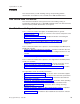
updated March 18, 2002 3. Press S2 to advance through the various parts of the printer adjustment steps. 4. Type 9 9 and then press S2 to exit. Table 2. Adjustment Procedures Using 4690 Operating System | Procedure Keying Sequence Print Current Adjustment Values - see Figure 14 on page 30. 7, 2, 1, S2 Character Alignment Procedure - see Figure 14 on page 30. 7, 2, 2, S2 DI Front Load Print Line Adjustment - see Figure 14 on page 30.
updated March 18, 2002 v v v v v v v Print current adjustment values - see Figure 14 on page 30. Character alignment procedure - see Figure 14 on page 30. DI front load print line adjustment - see Figure 14 on page 30. Document landscape adjustment - see Figure 14 on page 30.
updated March 18, 2002 TL1 CURRENT ADJUSTMENT VALUES H 5 = Character alignment TL5 = Top line front insert BL3 = Bottom line top insert CHARACTER ALIGNMENT PROCEDURE Press the key (1-9) that corresponds to the pair of H's that appear to be most aligned 5 = selected line Figure 14. Adjustment and Alignment Printouts 30 SureMark DBCS User’s Guide TL2 TL3 TL4 TL5 TL6 TL7 TL8 TL9 Measure from the top edge of this paper to the top of each print line.
updated March 18, 2002 4610 DBCS Installation Utility Diskette This utility is for both RS-232 and RS-485 operation. It includes: v The latest level of firmware for the printer v A README file that describes how to use the utility program.
updated March 18, 2002 a. Press Enter (OK) at the logo screen. b. Select the connection type (RS-485 or RS-232). For the RS-232 connection, also select the following: v Communications port (COM1, COM2, COM3, COM4) v Baud rate (9600 or 19 200) v Control flow (DTR/DSR or XON/XOFF) v IRQ test Refer to the communication mode selection switches located at the bottom rear of the SureMark printer when making the above selection. c. Press Enter (OK). d. Select the printer model, then select Enter (OK). e.
updated March 18, 2002 a. Press Done for confirmation if Download (Step 6h on page 32) was used. Press OK for confirmation if Selective Download (Step 6j on page 32) was used. b. Press C (Close) to close the dialog. c. Press Alt-X (Exit) to exit the menu. d. Press Enter to exit the utility. 8. When prompted, reinsert the 4610 DBCS Installation Utility Diskette, then press Enter. 9. Remove the diskette from drive A. 10. Press Ctrl-Alt-Delete to reboot the system.
updated March 18, 2002 Table 4. Font Files for DBCS Code Pages (continued) Code Page File Name Codeset Station Where to Download 949 Korea kormh16.fnt kormz16.fnt kormh24.fnt kormz24.fnt kudcz16.fnt kudcz24.fnt SBCS DBCS SBCS DBCS DBCS DBCS Impact Impact Thermal Thermal Thermal Thermal Impact code page 1 Impact DBCS Thermal code page 1 Thermal DBCS Impact DBCS UDC Thermal DBCS UDC 1381 Chinese PRC (Simplified) prcmh16.fnt prcmz16.fnt prcmh24.fnt prcmz24.fnt pudcz16.fnt pudcz24.
updated March 18, 2002 JPNMS932.CFG Code page 932, Japan, Mincho style KORMS949.CFG Code page 949, Korea CHNM1381.CFG Code page 1381, Chinese – PRC CHNM950N.CFG Code page 950, Chinese – Taiwan, normal impact SBCS CHNM950B.CFG Code page 950, Chinese – Taiwan, bold impact SBCS 4. The font file is created. The file name is XXX.FON, where XXX is the same as the configuration file. For example, when you run the 4610CVNT program with JPNMS932.CFG, the font file is JPNMS932.FON. 5.
updated March 18, 2002 c. d. e. f. g. Press Enter (OK). Select F10 (Menu). Select E (Edit). Select D (Edit Font File). Insert the font diskette, which includes the DBCS UDC font files. The DBCS UDC font file names for each code page and type of station are shown in Table 5. Table 5. UDC Font File Names for DBCS Code Pages Code Page File Name Station 932 (Japan) judcz16.fnt judcz24.fnt Impact Thermal 949 (Korea) kudcz16.fnt kudcz24.fnt Impact Thermal 1381 (PRC) pudcz16.fnt pudcz24.
updated March 18, 2002 4. Select Run Printer Utility for RS-485 or RS-232 connection. 5. Follow the displayed messages to complete the firmware update. a. Press Enter (OK) at the logo screen. b. Select the connection type (RS-485 or RS-232).
updated March 18, 2002 slot_number The SureMark slot number, which is usually 1. The slot number must be specified with decimal values only; hexadecimal values are not accepted. port_number The SureMark port number, which is usually 17. The port number must be specified with a decimal value. microcode_file Must be C:\POS\BIN\AIP46MC5.HEX. -Q Quiet mode installation (no progress information) 3. The SureMark flash update will take several minutes.
updated March 18, 2002 3. Follow the procedure in “4610 DBCS Installation Utility Diskette for Updating SureMark Firmware” on page 36, starting with Step 1, to complete the printer firmware update. 4. Reconnect the SureMark to the original host system unit using the original attachment cables.
updated March 18, 2002 The printer is reconfigured. 2. Press Ctrl-Alt-Delete to reboot the system. The system IPLs. To disable when emulation is currently enabled: 1. Select Disable Model 4 emulation. 2. Press Ctrl-Alt-Delete to reboot the system. The system IPLs. Enabling Emulation Using 4690 On-Line Terminal Diagnostics Note: 4690 OS Version 1 level 9740 or greater is required to use this utility. To set up Model 3 or Model 4 emulation using the 4690 On-Line Terminal Diagnostics: 1.
updated March 18, 2002 Printing Saved Data When the printer is offline in Model 3/4 emulation mode and the option for storing data to the printer was selected, it is possible to fill up the printer flash memory. When the memory is full, a printer error indicates the journal station is out of paper. You can empty the printer buffer by printing out the data that is stored in the flash memory. The data prints on the customer receipt station.
updated March 18, 2002 Enabling Epson Emulation To enable emulation of an Epson single-station printer on a single-station SureMark printer, you must set switch 3 on the main logic card. See Figure 15. OFF 1 2 3 4 RS-232 mode switches Cash drawer connector Figure 15. Switch for Epson Emulation Limitations for Epson Emulation The following limitations must be considered when using the SureMark printer to emulate an Epson single-station printer.
updated March 18, 2002 b. Press Ctrl-Alt-Delete to reboot the system. The system IPLs. Proportional Font Conversion Utility As part of its support for proportional fonts, IBM provides three TrueType fonts and a utility that you can use to convert the fonts to files that the SureMark printer can use. The application and instructions for downloading the converted fonts are available from the Retail Store Solutions Web site. See “Resources on the Internet” for more information.
updated March 18, 2002 44 SureMark DBCS User’s Guide
updated March 18, 2002 Part 2. Models TI5 and TG5 This part contains operational, testing, and problem determination information for SureMark Models TI5 and TG5 is a thermal/impact printer with DBCS support. © Copyright IBM Corp.
updated March 18, 2002 46 SureMark DBCS User’s Guide
updated March 18, 2002 Chapter 4. Operation (Models TI5 and TG5) Operating Controls and Indicators Ribbon Loading . . . . . . Paper Loading . . . . . . . Thermal Printhead Cleaning . . . . . . . . . . . . . . . . . . . . . . . . . . . . . . . . . . . . . . . . . . . . . . . . . . . . . . . . . . . . . . . . . . . . . . . . . . 47 49 51 53 Note: All covers must be installed on the SureMark printer during operation.
updated March 18, 2002 Figure 17. Inserting Documents Figure 18 and Figure 19 on page 49 show the printable area on an inserted document for both portrait and landscape. Figure 18.
updated March 18, 2002 Figure 19. Printable Area of an Inserted Document (Landscape) Ribbon Loading 1. Open the ribbon cover. As the cover is opened, the printhead moves to a position where you can easily load a ribbon. Figure 20. Opening the Ribbon Cover 2. If there is already a ribbon cartridge installed, remove it by lifting it straight up. Chapter 4.
updated March 18, 2002 Note: You might need to grab the body of the cartridge rather than the top to remove it. Figure 21. Ribbon Cartridge Loading 3. Maintain ribbon tension by turning the ribbon cartridge knob as shown in Figure 21. Lower the cartridge into position until the notches on its sides snap into place on the printer guides. Once the cartridge is in place, turn the knob until the ribbon slides into place between the printhead and the ribbon shield.
updated March 18, 2002 Paper Loading 1. Open the paper cover. 2. If there is any unused paper or if there is an empty paper roll core in the paper roll bucket inside the printer, remove it before inserting a new paper roll. You can throw the core in the trash can. Figure 23. Paper Cover – Models TI5 and TG5 Note: Refer to the label on the inside of the paper cover for a diagram of how to load paper. 3. See Figure 24 on page 52 and place the paper roll into the paper roll bucket as shown.
updated March 18, 2002 Not Correct Thermal Platen Correct Paper Roll Paper Roll Core Figure 24. Paper Loading Path –: Models TI5 and TG5 4. Place the leading edge of the paper over the metal guide. See Figure 24. 5. Close the paper cover. 6. Press the customer receipt feed button to advance the paper to verify that the paper is feeding correctly. Feed 30 cm (about 1 ft) of paper through to test for correct alignment.
updated March 18, 2002 Thermal Printhead Cleaning The thermal printhead can be cleaned whenever print quality deteriorates. 1. Open the paper cover. 2. Using a cotton swab soaked in isopropyl alcohol, gently wipe the printhead several times on its print line and on the surrounding area. See Figure 25. 3. Wipe off any residual alcohol with a dry swab. If print quality does not improve after cleaning the thermal printhead, call for service.
updated March 18, 2002 54 SureMark DBCS User’s Guide
updated March 18, 2002 Chapter 5. Testing and Problem Analysis – Models TI5 and TG5 DANGER To avoid a shock hazard, do not connect or disconnect an y cables or perform installation, maintenance, or reconfiguration of this product during an electrical storm. DANGER To avoid shock hazard: The power cord must be connected to a properly wired and earthed receptacle. Any equipment to which this product will be attached must also be connected to properly wired receptacles.
updated March 18, 2002 Printer Ready LED Customer Receipt Feed Button Document Present LED Document Feed Button 2. Check the status of the Printer Ready indicator: Printer ready indicator ON: The Power On Self Test completed successfully. Printer ready indicator OFF or blinking: The POST failed. 3. If the POST fails or if you suspect problems with your system, see “Problem Determination” on page 59. 4. See “Offline Tests” and run the offline tests.
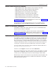
updated March 18, 2002 | 2. Press and hold both buttons to enter offline mode. When the printer ready indicator begins blinking, release both buttons. 3. Press and release the document feed button to print the test pattern. The test pattern includes all printable characters in the resident code page, printed in the default font. 4. See Figure 26 and verify that your printer has printed correct information for your model and configuration: v Model type (double-byte enabled for Models TI5 and TG5).
updated March 18, 2002 6. The feature enabled lines will appear only when the feature is installed. 7. These lines break at different points for the test pattern printed in the document insert (DI) station. 8. This section contains printer usage statistics that you can use for problem determination. 9. The line across the bottom should be solid with no blank spaces.
updated March 18, 2002 Resetting the Printer - Offline 1. Press and hold both buttons (Customer Receipt Feed button and Document Feed button) to enter offline mode. Release both buttons when the Printer Ready indicator begins to blink. 2. Open the customer receipt cover, then close it. The printer resets. Problem Determination Any problems that arise with a SureMark printer are either software errors or hardware failures.
updated March 18, 2002 60 SureMark DBCS User’s Guide
updated March 18, 2002 Part 3. Models TF7 and TM7 This part contains operational, testing, and problem determination information for SureMark models TF7 and TM7. These models are the single-station SureMark printers with DBCS support. © Copyright IBM Corp.
updated March 18, 2002 62 SureMark DBCS User’s Guide
updated March 18, 2002 Chapter 6. Operation (Models TF7 and TM7) Operating Controls and Indicators . . . . . . . . . . . . . . . . . . 63 Paper Loading . . . . . . . . . . . . . . . . . . . . . . . . . 63 Thermal Printhead Cleaning . . . . . . . . . . . . . . . . . . . . 66 Note: All covers must be installed on the SureMark printer during operation. Operating Controls and Indicators There is one triangular-shaped button and one light-emitting diode (LED) indicator located on top of the printer.
updated March 18, 2002 Top cover Sphere Paper roll Metal Spring Bucket Figure 28. Paper Loading Path 4. Pull the end of the paper up over the paper roll and toward the back of the printer. Note: Refer to the label on the inside of the bottom cover for a diagram of how to load paper. 5. Close the paper cover. 6. Press the customer receipt feed button to advance the paper and verify that the paper is feeding correctly. Feed 30 cm (about 1 ft) of paper through to test for correct alignment.
updated March 18, 2002 Top cover Sphere Paper roll Metal Spring Bucket Figure 29. Paper Loading Path (Models TF7 and TM7) Attention: Do not pull the receipt paper out of the printer with the paper access cover closed. This might cause partial lines of print. Use the customer receipt feed button to advance the receipt. Chapter 6.
updated March 18, 2002 Thermal Printhead Cleaning The thermal printhead can be cleaned whenever print quality deteriorates. 1. Open the paper cover. 2. Using a cotton swab soaked in isopropyl alcohol, gently wipe the printhead several times on its print line and on the surrounding area. See Figure 30. 3. Wipe off any residual alcohol with a dry swab. If print quality does not improve after cleaning the thermal printhead, call for service. Detail View of Thermal Print Head Thermal Print Line Figure 30.
updated March 18, 2002 Chapter 7. Testing and Problem Analysis – Models TF7 and TM7 DANGER To avoid a shock hazard, do not connect or disconnect an y cables or perform installation, maintenance, or reconfiguration of this product during an electrical storm. DANGER To avoid shock hazard: The power cord must be connected to a properly wired and earthed receptacle. Any equipment to which this product will be attached must also be connected to properly wired receptacles.
updated March 18, 2002 Top cover Printer ready LED Customer receipt feed button 2. Check the status of the Printer Ready indicator: Printer Ready indicator ON: The power-on self test completed successfully. Printer Ready indicator OFF or blinking: The POST failed. 3. If the POST fails or if you suspect problems with your system, see “Problem Determination” on page 70. 4. See “Offline Test” and run the offline test.
updated March 18, 2002 T The Printers S/N is 12345678 1 Microcode EC level is 30 Serial Interface: RS232 Serial Interface : 19.2K Baud, XON / XOFF Double Byte Character Sets |"#$%&'()*+,-./0123456789:;<->?ABCDEFGHIKJK LMNOPQRSTUVWXYZ[\]^_ abcdefghijklmnopqrstuvw xyz{|}~.
updated March 18, 2002 Resetting the Printer - Offline To reset the printer: 1. Open the top cover. 2. Power off the printer using the power on/off switch that is located in the right front corner of the printer. 3. Power on the printer. Problem Determination Any problems that arise with a SureMark printer are either software errors or hardware failures. This section contains information to help you determine the cause of a problem and how to solve it.
updated March 18, 2002 Part 4. Appendixes © Copyright IBM Corp.
updated March 18, 2002 72 SureMark DBCS User’s Guide
updated March 18, 2002 Appendix A. Consumable Supplies Paper Specifications . . . . . . . . . . . . . Thermal Paper . . . . . . . . . . . . . . Document Insert Forms (Models TI5 and TG5 Only) Single and Multipart Form Specifications . . . Print Ribbons (Models TI5 and TG5 Only) . . . . . . . . . . . . . . . . . . . . . . . . . . . . . . . . . . . . . . . . . . . . . . . . . . . . . .
updated March 18, 2002 Document Insert Forms (Models TI5 and TG5 Only) The printers will accommodate single and multipart forms.
updated March 18, 2002 Single and Multipart Form Specifications Specification Value Minimum width: 50 mm (2 in.) Maximum thickness of multipart forms: 0.47 mm (0.0185 in.) Maximum thickness of front sheet, multipart forms: 0.08 mm (0.003 in.) Minimum thickness of single-part form: 0.10 mm (0.004 in.) Note: Test all forms in the printer to ensure acceptable performance prior to buying a significant quantity. There should be no binding holes or other holes within 10 mm (0.4 in.
updated March 18, 2002 76 SureMark DBCS User’s Guide
updated March 18, 2002 Appendix B. Technical Information General Description . . . . . . . . . . Specifications . . . . . . . . . . . . Memory Units . . . . . . . . . . . . Immediate Commands . . . . . . . . . Voltage Conversion Circuitry . . . . . . . RS-485 Serial I/O Parameters . . . . . . Cash Drawer Connector Pin Assignments . . RS-232 Connector Pin Assignments . . . . RS-232 Parameters . . . . . . . . . . USB Connector Pin Assignments . . . . . Code Page Definitions . . . . . . . . .
updated March 18, 2002 Table 8. Station Characteristics Characteristic Customer Receipt Station Document Insert Station Speed (see note following table) SBCS characters: 39.2 lps at 6 lpi, SBCS characters: 52 lps at 8 lpi DBCS characters: 50 lps at 7.7 lpi 4.3 lps Paper Width TI5/TG5 – 80 mm (3.15 in.) TF7/TM7 – 90 mm (3.54 in.
updated March 18, 2002 Memory Units Random access memory (RAM) is used for storing the image data for the thermal printhead and program code. It is also used for storing incoming data from the communication port.
updated March 18, 2002 v When operating in RS-485 mode, the +38 V dc is converted to +24 V dc and the +5 V dc is passed straight through. v When operating in RS-232 or USB mode or RS-485 mode in Japan, the +24 V dc is passed through and is also converted to +5 V dc. | | | | Note: Both voltage sources should not be connected to the printer at the same time, even if one of the sources is powered off. System damage could occur under these conditions.
updated March 18, 2002 3 4 5 6 7 8 9 Receive DTR (Not connected on 3-wire cable) Signal Ground DSR (Not connected on 3-wire cable) Not Connected Not Connected Not Connected See “Description of Models” on page 4 for the cable part number. RS-232 Parameters Protocol DTR/DSR mode or XON/XOFF mode. Dip switch selectable. Baud rate 9600 or 19 200, selectable by DIP switch Start 1 bit Data 8 bits Parity None Stop 1 bit Table 10.
updated March 18, 2002 | | | 2 3 4 Minus data Plus data Ground | The powered USB connector has the following pin functions: | | | | | | | | | Pin 1 2 3 4 5 6 7 8 | See “Description of Models” on page 4 for the cable part numbers.
updated March 18, 2002 Generic Code Page ° Pt ¥ § Figure 32. Printer’s Resident Character Set - Generic Code Page Appendix B.
updated March 18, 2002 Code Page 437 Figure 33.
updated March 18, 2002 Code Page 858 Hex 1st 2nd 2_ 3_ 4_ 5_ 6_ 7_ 8_ 9_ A_ B_ C_ D_ E_ F_ _0 . 0 @ P . p Ç É á . . ð Ó . _1 ! 1 A Q a q ü æ í . . Ð _2 " 2 B R b r é Æ ó . . Ê Ô . _3 # 3 C S c s â ô ú . . Ë Ò . _4 $ 4 D T d t ä ö ñ . . õ . _5 % 5 E U e u à ò Ñ Á . È C Õ . _6 & 6 F V f v å û G Â . Í µ ÷ _7 ' 7 G W g w ç ù g À . Î Þ . _8 ( 8 H X h x ê ÿ ¿ I Ï þ .
updated March 18, 2002 Code Page 860 Figure 35.
updated March 18, 2002 Code Page 863 Figure 36. Code Page 863 Appendix B.
updated March 18, 2002 Code Page 865 Figure 37.
updated March 18, 2002 Code Page 932 Hex1st 2nd 2_ _0 3_ 4_ 5_ 0 @ P 6_ 7_ p 8_ 9_ A_ £ B_ C_ D_ E_ F_ _1 ! 1 A Q a q _2 " 2 B R b r _3 # 3 C S c s _4 $ 4 D T d t _5 % 5 E U e u _6 & 6 F V f v _7 ' 7 G W g w _8 ( 8 H X h x _9 ) 9 I Y i y _A * : J Z j z _B + ; K [ k { _C , < L l | _D - = M _E . > N ^ n \ _F / ? O _ o ~ ] m } Figure 38. Code Page 932 Notes: 1.
updated March 18, 2002 Code Page 949 Hex1st 2nd 2_ _0 3_ 4_ 5_ 0 @ P 6_ 7_ 8_ 9_ A_ B_ C_ D_ E_ F_ p _1 ! 1 A Q a q _2 " 2 B R b r _3 # 3 C S c s _4 $ 4 D T d t _5 % 5 E U e u _6 & 6 F V f v _7 ' 7 G W g w _8 ( 8 H X h x _9 ) 9 I Y i y _A * : J Z j z _B + ; K [ k { _C , < L W l | _D - = M ] _E . > N ^ n _F / ? O _ o m } ~ Figure 39. Code Page 949 Notes: 1.
updated March 18, 2002 Code Page 950 Hex1st 2nd 2_ _0 3_ 4_ 5_ 0 @ P 6_ 7_ 8_ 9_ A_ B_ C_ D_ E_ F_ p _1 ! 1 A Q a q _2 " 2 B R b r _3 # 3 C S c s _4 $ 4 D T d t _5 % 5 E U e u _6 & 6 F V f v _7 ' 7 G W g w _8 ( 8 H X h x _9 ) 9 I Y i y _A * : J Z j z _B + ; K [ k { _C , < L \ l | _D - = M ] _E . > N ^ n _F / ? O _ o m } ~ Figure 40. Code Page 950 Notes: 1.
updated March 18, 2002 Code Page 1381 Hex1st 2nd 2_ _0 3_ 4_ 5_ 0 @ P 6_ 7_ 8_ p £ _1 ! 1 A Q a q _2 " 2 B R b r _3 # 3 C S c s - _4 $ 4 D T d t | _5 % 5 E U e u _6 & 6 F V f v _7 ' 7 G W g w _8 ( 8 H X h x _9 ) 9 I Y i y _A * : J Z j z _B + ; K [ k { _C , < L \ l | _D - = M ] _E . > N ^ n _F / ? O _ o m 9_ A_ B_ C_ D_ E_ F_ } ~ Figure 41. Code Page 1381 Notes: 1.
updated March 18, 2002 Character Fonts This section describes font capabilities.
updated March 18, 2002 v 8 ≤ dot width ≤ 32 v 8 ≤ dot height ≤ 32 Notes: 1. Any of the thermal printing fonts can be scaled up to eight times the defined width and eight times the defined height. The scaling factor for the width does not have to equal the scaling factor for the height. For example, you could specify twice the width and five times the height. 2. For 80-mm paper, the cash receipt print line is 72 mm (2.83 in.) long. There are 576 dots per line and 203 dots per inch. 3.
updated March 18, 2002 – For SBCS code pages 932, 950, 1381: 8 full-dot wide character + 3 half-dot space Font A: 150 half-dots per inch ⇒ 24 characters per line Font B: 120 half-dots per inch ⇒ 19 characters per line You can choose the character size of the one user-defined character set (code page) within the following parameters: v 4 ≤ half-dot width ≤ 16 v 4 ≤ dot height ≤ 16 Notes: 1. Any of the impact printing fonts can be printed double-wide, double-high, or both double-wide and double-high.
updated March 18, 2002 96 SureMark DBCS User’s Guide
updated March 18, 2002 Appendix C. RS-232 Programming Information RS-232 Commands Summary by Function . . . . Alphabetized RS-232 Commands Summary . . . . System Commands . . . . . . . . . . . . . Exercise Program . . . . . . . . . . . . Verify Previous Commands Completed . . . . Status Request . . . . . . . . . . . . . Extended Address Command – Request Printer ID Preset or Onetime-Set Commands . . . . . . . Download Graphics (Logo) Commands . . . . Example: n1 = 2 & n2 = 2 . . . . . . . .
updated March 18, 2002 Select Character for Reprinted Lines . . . . . . . . . . Reinitialize the Printer . . . . . . . . . . . . . . . . Enable or Disable the Feed Buttons (Models TI5 and TG5 Only) Enable or Disable the Beeper (Models TF7 and TM7 Only) . . Enable or Disable Upside-Down Printing . . . . . . . . . Select Character Size for Scalable Fonts . . . . . . . . . Fix Font Matrix . . . . . . . . . . . . . . . . . . Print Logo Inline . . . . . . . . . . . . . . . . . .
updated March 18, 2002 Status Byte 7 . . . . . . . . . . . . . . . . . . . . . . . . 162 Status Byte 8 . . . . . . . . . . . . . . . . . . . . . . . . 162 Appendix C.
updated March 18, 2002 This appendix applies only to SureMark printers that attach to a POS system with an RS-232 cable connection.
updated March 18, 2002 Table 12. RS-232 Commands Organized by Function (continued) Description Command Page Set or cancel double-wide mode ESC W n:ehp1.
updated March 18, 2002 Table 12.
updated March 18, 2002 Table 12.
updated March 18, 2002 Alphabetized RS-232 Commands Summary Table 13.
updated March 18, 2002 Table 13. RS-232 Commands in Alphabetical Order (continued) Description Command Page Print, form feed, and cut the paper (FF) FF or X'0C'.
updated March 18, 2002 Table 13.
updated March 18, 2002 System Commands Exercise Program RS-232 Syntax: ESC x or X'1B;78' Purpose: This tests printing functions of the printer. A test message is printed. (See Figure 26 on page 57.) If there is a document in the printer, the test message prints on the document. Otherwise, it prints at the customer receipt station.
updated March 18, 2002 Status byte 5, bit 0 is set to 1 when responding to the extended address command. (See “Status Summary” on page 160.) where: | | | Byte 1 | | Byte 2 Device type = 30 Device ID.
updated March 18, 2002 Preset or Onetime-Set Commands The SureMark printer has commands to specialize and tune each printer to improve its usability, performance, and uniqueness. This flexibility is provided through the use of flash erasable programmable read-only memory (flash EPROM) and an electrically erasable programmable read-only memory (EEPROM). Data in these memory devices will stay valid until it is redefined.
updated March 18, 2002 1 ≤ n2 ≤ 5 for an impact logo. data The data to form the graphics image. The number of data bytes for the image is n1 × n2 × 8 Purpose: To store all-points-addressable print messages. Remarks: These messages can be positioned on the page using the commands for setting positions. Decimal values are shown, but all parameter values (logo number, n1, n2) must be hex values when sent to the printer. The dot density of these messages is specified when the message is printed.
updated March 18, 2002 For Impact Graphics - Defined as: X'1D2A020202FF00FF00FF00FF00FF00FF00FF00FF00 00FF00FF00FF00FF00FF00FF00FF00FF' Error Conditions: Flash EPROM load error - Verify the sector was erased before downloading images. Memory sector is full - The sector can store up to 64 KB of graphics data, after which the sector is full. Predefine Messages RS-232 Syntax: GS : message_num data GS : or X'1D3A;message_num;data;1D3A' where: message_num The message number being stored.
updated March 18, 2002 1. X'1D3A06' 2. ’Welcome to Our Store’ X'0D' 3. X'1D5E03' (This prints the message that has been stored at location 3. The message cannot have a X'1D5Exx' in it, because that would be more than one level of nesting.) 4. ’Is Your Cashier Today’ X'0D' 5.
updated March 18, 2002 v Once characters are downloaded to the printer, they remain valid until you redefine them. This is true even if power to the printer is removed. v Before the characters are defined, the sector of the flash EPROM which stores this data must be erased. (See “Erase Flash EPROM Sector” on page 121.) Also, the character matrix for the code page must have already been defined. (See Table 15 on page 123, MCT# 3, 4, and 5.
updated March 18, 2002 Defined as: X'1B26014848 C0C0C0C0C0C0C0C0C0C0C0C0C0C0FFC0FFC0F C0C0C0C0C0C0C0C0C0C0C0C0C0C0C0C0C0C0' The above statement defines character X'48' as an ’H’. Note: The number of data bytes = 2 × dot height (20) = 40 bytes. Proportional Font RS-232 Syntax: ESC & s n m data or X'1B;26;s;n;m;data' where: s The character set being defined. 1 User-defined thermal code page 1. 3 User-defined thermal code page 3. n The beginning ASCII address of the characters being defined.
updated March 18, 2002 v ASCII characters 0 through 31 are reserved for RS-232 functions and cannot be defined. v See Appendix E, “Proportional Fonts” on page 165 for suggestions about how to implement proportional fonts. Limitations: The memory required for proportional fonts is much greater than the memory that was required for user-defined fonts. Therefore, when code page 1 (or 3) is set up as proportional, code page 2 (or 4) is not valid.
updated March 18, 2002 0000111100000000 0001111110000000 0011111111000000 0111000011100000 0110000001100000 1100000000110000 1100000000110000 1100000000110000 1100000000110000 1100000000110000 1100000000110000 1100000000110000 1111111111110000 1111111111110000 1100000000110000 1100000000110000 1100000000110000 1100000000110000 1100000000110000 1100000000110000 1100000000110000 1100000000110000 0000000000000000 0000000000000000 0000000000000000 0000000000000000 0000000000000000 0000000000000000 000000000000
updated March 18, 2002 Example: 11 half-dots wide (or 5.5 full dots) × 9 high Defined as: X'1B26034141FO00080014000200110000081100020014000800F000' The above statement defines character X'41' as an ‘A’. Note: The number of data bytes = 2 × dot width (11) = 22 bytes. Error Conditions: Flash EPROM load error - Verify the sector was erased before downloading images. Download Double-Byte Characters RS-232 Syntax: ESC ( s n data or X'1B;28;s;n;data' where: s The character set being defined.
updated March 18, 2002 v You must erase the sector of the flash EPROM where this data is stored before you define the characters. (See “Erase Flash EPROM Sector” on page 121.) You must also predefine the character matrix for the impact DBCS code. (See “Microcode Tolerance (MCT) Information - Request” on page 123.) v The flash EPROM sector 6 contains the double-byte character set for both the thermal and impact printheads.
updated March 18, 2002 For example: Data that defines a character at X'8141' as a large box is: X’1B;28;00;01;81;41;FF;FF;FF;FF;FF;FF; C0;00;03;C0;00;03;C0;00;03;C0;00;03;C0;00;03;C0;00;03; C0;00;03;C0;00;03;C0;00;03;C0;00;03;C0;00;03;C0;00;03; C0;00;03;C0;00;03;C0;00;03;C0;00;03;C0;00;03;C0;00;03; C0;00;03;C0;00;03;FF;FF;FF;FF;FF;FF’ Impact Printhead (s=1) The width of these characters is always 16.
updated March 18, 2002 P 0 S 0 P 0 S 0 P 0 S 0 P 0 S 0 P 0 S 0 P 0 S 0 P 0 S 0 P 0 S 0 0 0 0 0 0 0 0 0 0 0 0 0 0 0 0 0 0 0 0 0 0 0 0 0 0 0 0 0 0 0 0 0 0 0 0 0 0 0 0 0 0 0 0 0 0 0 0 0 0 0 0 0 0 0 0 0 0 0 0 0 0 0 0 0 0 0 0 0 0 0 0 0 0 0 0 0 0 0 0 0 0 0 0 0 0 0 0 0 0 0 0 0 0 0 0 0 . . . . . . X . . . . . . . . . X . . . . . X . X . X .X . .. X .X . .. X .X . .. X .X . X . X . X . X . X . X . X . X . X . X . X X X X . . . . . . X . X X . . . . . . . X . . . . . .
updated March 18, 2002 X X X X X X X X X X X X X X X X X X X X X X X X X X X X X X X X X X X X X X X X X X X X X X X X Flash Storage Write RS-232 Syntax: ESC ’ m add data or X'1B;27;m;add;data' where: m = number of data bytes to store Add = 3-byte address where data bytes are to be stored Error Conditions: Flash EPROM load error - Verify the sector was erased before downloading images.
updated March 18, 2002 05 Sector 5 - flash storage 06 Sector 6 - DBCS character storage 07 - FF Reserved Purpose: To erase the flash EPROM before downloading the data into the printer. Remarks: The command should only be sent to the printer when the buffer is empty (status byte 2, bit 6). No other commands should be sent until this command is complete. Status byte 3, bit 7 (command complete bit) is set to show erasing is finished and the command is complete.
updated March 18, 2002 where: n Microcode tolerance (MCT) that is being adjusted h The high-order byte of MCT data l The low-order byte of MCT data Purpose: The microcode tolerance (MCT) information is used to make adjustments to the printer’s microcode. MCT data is nonvolatile data stored in the printer EPROM that is specific to a printer. For example, an MCT parameter can be defined to adjust for mechanical tolerances which cause a print line to not be centered on a receipt.
updated March 18, 2002 Table 15.
updated March 18, 2002 DBCS Address Vectors RS-232 Syntax: ESC S n or X'1B;53;n' where: n Specifies the DBCS address vector. v 33 for address vector 1 v 34 for address vector 2 v 35 for address vector 3 Purpose: To determine the address ranges that are assumed for the DBCS and SBCS code pages. Remarks: v The DBCS address vector value is sent over the serial line in status bytes 9 and 10. v The vector ranges should be stored in the printer at the time of download. v All ranges are for DBCS addresses.
updated March 18, 2002 Bit # ↓ 4 5 6 MSB 7 Function Double-high Double-wide Inverted Mode Underlined Bit=0 Cancel Cancel Cancel Cancel Bit=1 Set Set Set Set Thermal yes yes yes yes Impact yes yes no no Table 16.
updated March 18, 2002 n=01 Set double-wide mode Default: n = 00 Set or Cancel Double-High Mode RS-232 Syntax: ESC h n or X'1B;68;n' where: n=00 Cancel double-high mode n=01 Set double-high mode Default: n = 00 Purpose: For better print quality with double-high characters in the document station. Remarks: See “Set or Cancel Unidirectional Printing” on page 135.
updated March 18, 2002 n=00 Cancel Invert Mode n=01 Set Invert Mode Default: n = 00 Remarks: This is valid in the customer receipt station only. Set or Cancel Emphasized Printing RS-232 Syntax: ESC G n or X'1B;47;n' where: n=00 Cancel Emphasized Mode n=01 Set Emphasized Mode Default: n = 00 Remarks: This must be at the beginning of a print-line in the document portrait station. It is enabled for the entire line.
updated March 18, 2002 4 5 6 7 Reserved Reserved Reserved Reserved Default: n = 02 Remarks: See “Document Handling” on page 157. Only one station can be set at a time. If you select more than one station, the command is ignored. Select User-Defined or Resident Character Sets RS-232 Syntax: ESC % n or X'1B;25;n' where: n=00 Select resident character sets n=01 Select user-defined character sets Default: n = 00 Remarks: See “Character Fonts” on page 93 and “Download User-Defined Characters” on page 112.
updated March 18, 2002 where: n The number of dot-spaces in the thermal print station or half-dot spaces in the impact print station. Default: n = 03 Maximum: n = 08 Remarks: If you select double-width printing, the space to the right of each character is doubled. Set Inter-Character Spacing – DBCS RS-232 Syntax: ESC T n or X'1B;52;n' where: n The number of dot-spaces in the thermal print station or half-dot spaces in the impact print station.
updated March 18, 2002 LSB 0 1 2 3 4 5 6 7 Reserved Customer Receipt Station Document Station - Portrait Mode Document Station - Landscape Mode Reserved Reserved Reserved Reserved Purpose: This command is used for setting the line spacing, margins, and tabs. Remarks: More than one station can be selected at the same time if the settings are common to all of the selected stations.
updated March 18, 2002 in-between the lines (4 steps). The actual lines-per-inch will be adjusted. For example, if the printer is set to 1/6-inch line spacing, the printer will line feed 8 steps in-between each line, and the 4 steps inside of the line. The result is 12 steps per line or 4 lines per inch.
updated March 18, 2002 Set Sheet Eject Length RS-232 Syntax: ESC C n or X'1B43;n' where: n Specifies the number of line feed steps using minimum units moved when a FF is sent in the receipt station. In the document station, an eject will feed until the document has exited the lower document sensors - this length is not used. Default: n = X'A0' (160 decimal) Maximum: 255 steps (X'FF') This value is stored in the EEPROM in the printer so that it is not lost when the printer is reset.
updated March 18, 2002 Default: n1 = 0, n2 = 0 Remarks: In the customer receipt station, 1 mm = 8 dots. In the document station, 1 inch = 150 half-dots (75 dots). n1 and n2 are hex values. Use this formula to get the decimal equivalent: (n1 × 256) + n2. If the number exceeds the printable area, it is ignored. The maximum value for the customer receipt station is 576. The maximum value for the document insert station is 474. In the customer receipt station, this number is rounded back to a factor of 8.
updated March 18, 2002 04 Align Column Right Default: n = 00 Remarks: v Values 00, 01, and 02 are only valid at the beginning of a line. v Tabs are only valid when printing is aligned to the left. If tabs are used when left alignment is not used, results can be unpredictable. (See “Tab to Next Tab Stop” on page 152.) v Alignment is relative to the left margin. v To use the Align Column Right command: 1. Send the characters that you want to be left aligned. 2. Send the Align Column Right command. 3.
updated March 18, 2002 where: n Selects the function.
updated March 18, 2002 This value is stored in the EEPROM in the printer so that it is not lost when the printer is reset. Status Sent to System RS-232 Syntax: ESC ) n or X'1B29;n' where: n Select function.
updated March 18, 2002 Setting Print mode Print station selected User-defined/resident character sets Code page Intercharacter spacing (SB) Rotated characters Station for line spacing Line spacing all stations Tab positions Left margin Relative position Align positions Unidirectional printing Horizontal size of bar code Vertical size of bar code Position of HR Font for HRI Default Value 00 02 01 02 03 00 02 Six LPI Every 100 dots 00 00 00 00 03 A2 00 00 Error Conditions: None Enable or Disable the Feed B
updated March 18, 2002 n2 Sets the beeper volume and tone. Bits 0–3 The note. Bit 0 is the LSB. Bits 4–5 The octave. Bits 6 Reserved. Bit 7 Volume. 0 = loud, 1 = soft.
updated March 18, 2002 Purpose: When the printer is wall-mounted, the front of the printer points up. Therefore, the print data appears upside down when data is printed normally. This command allows the data to be right-side up as it comes out of the printer. Remarks: v When upside-down printing is enabled, the last line of data must be sent to the print first. v This command is valid only at the beginning of a print line.
updated March 18, 2002 Fix Font Matrix RS-232 Syntax: ESC : n or X'1B 3A n' where: n The character width to which all proportional characters will be adjusted. The range of valid values is 7
updated March 18, 2002 RS-232 Syntax: GS ; n or X'1D 3B n' where: n X'0' Disable two-color printing. X'1' Enable color printing using print parameter set 1. X'2'–X'FF' Select the print parameters to be defined. Purpose: To enable two-color printing and select the print parameters that are best suited for the paper selected. Remarks: v New parameters will be defined as new color papers become available. v The speed of printing will change depending on the print parameters.
updated March 18, 2002 v This command will increment status byte 6. v Printing will not start until X'00' is received, or the end of a data packet in RS-485. v Data after any invalid character for a particular bar code will be discarded. The printer will continue to wait for X'00'. v If X'00' or an invalid character is received before the required number of data bytes, zeros will be inserted following the data until the required number is reached (for UPC-A, UPC-E, JAN13, and JAN8).
updated March 18, 2002 | Table 18.
updated March 18, 2002 | Table 18.
updated March 18, 2002 n The horizontal magnification of the line width in the bar code, (2 ≤ n ≤ 4). Default: n = 03 Note: The last valid value is kept when an invalid value is sent. Select Bar Code Height RS-232 Syntax: GS h n or X'1D68;n' where: n The dot height of the bar code, (1 ≤ n ≤ 255).
updated March 18, 2002 Note: The last valid value is kept when an invalid value is sent. Print PDF417 Bar Code RS-232 Syntax: GS P data NUL or X'1D;50;data;00' where: data The ASCII representation of the characters to be printed. Remarks: Valid only at the beginning of a line. Printing will not start until a X'00' is received. This command will increment status byte 6. The maximum number of characters to be encoded is 1000.
updated March 18, 2002 For 9 ≤ n1n2 ≤ 400, the ECC level is assumed as a percentage of the codewords in the bar code. Select Aspect Ratio PDF417 Bar Code RS-232 Syntax: GS S r;c or X'1D;53;r;c' where: r The height dimension for the ratio; 1 ≤ r ≤ 9. c The width dimension for the ratio; 1 ≤ c ≤ 9. Default: r = 1, c = 2 Remarks: This is not an exact ratio. The image will get as close as possible to the ratio. However, the maximum width of an image is 12 columns and the maximum height is 90 rows.
updated March 18, 2002 Print and Line Feed RS-232 Syntax: CR or X'0D' Purpose: Prints data in the print buffer and feeds the paper by a preset amount. Remarks: There is an MCT to enable or disable this command. The default is to disable or ignore the CR command.
updated March 18, 2002 Print Graphic Messages Select and Print a Graphics (Logo) Command RS-232 Syntax: ESC * d w h data or X'1B2A;d;w;h;data' where: d Dot density. 00 Normal Print - 200 dpi in the receipt station, 150 dpi in the document station. Note: In the document station, this takes three passes of the printhead for a logo that is 8 dots high. 01 Double wide - 100 dpi in the receipt station, 75 dpi in the document station.
updated March 18, 2002 2. Send all the data. 3. Release the buffer. The left margin will be rounded down to a factor of 8. For example, if the margin = 74, the logo starts at 72. Retries are not attempted on print errors. Valid at the beginning of the line only. When printing in the document station, a line feed command must be sent to advance the paper past the last line of the logo.
updated March 18, 2002 Remarks: The margin is ignored if it causes the logo to overrun the line length. Printing this message in the document station at 150 dpi will take three passes of the printhead. These messages can be positioned on the page using the commands for setting positions. Valid at the beginning of the line only. This command is not valid in landscape mode. This command will increment status byte 6. Retries will not be attempted on print errors.
updated March 18, 2002 Return Home (Select Printhead Location) RS-232 Syntax: ESC < n or X'1B3C;n' where: n The print-head position: 00 Document home position 01 Open document throat position. The DI station throat will automatically be closed if the CR station is exercised. 02 Reserved 03 Left home position 04 Refined document home position. This can be used to recover from a home error.
updated March 18, 2002 Remarks: Printing will be suspended while a cash drawer is being opened. Retrieve the Flash Storage RS-232 Syntax: ESC 4 m add or X'1B34;m;add' where: m One-byte count of the bytes to be returned add Three-byte address of the first byte to be returned Purpose: Retrieve data from user flash storage. Remarks: One byte will be returned if a byte count of X'00' is specified.
updated March 18, 2002 RS-232 Syntax: X'10 05 40' 2. Execute the Retrieve Printer Usage Statistics command. 3. Multiply the returned value by the factor given in Table 19 to get the actual printer statistic. Table 19.
updated March 18, 2002 Real-Time Requests RS-232 Syntax: DLE ENQ m or X'1005:n' where: m Specifies the ASCII command character n Specifies the hexadecimal command character m n Description 1 31 Release the print buffer for printing. This should be sent after an error has occurred and the print buffer is held. If an error occurred during the transaction that was being held, the printer sends back the line number with the error and the error status.
updated March 18, 2002 After the printer resets, it defaults to not sending status unless requested. If an error occurs, the printer appears hung, unless a status is requested. If unsolicited status is enabled, the printer sends the error to the system as soon as it occurs. Note: If transparent XON/OFF is disabled, X'10', X'11', and X'13' can be imbedded in returned status and data. (See “XON/XOFF Control” on page 24.) To re-enable the printer, the printer must be reset.
updated March 18, 2002 Portrait Mode This is a suggested way of document handling: 1. ESC f (x) (y): Set up document wait time x Time the printer should wait from receiving a print line for the document station until the document is inserted. If the document has not been detected by the time the wait time ends, a document error is sent to the system but the system continues to wait for a document to be inserted.
updated March 18, 2002 v v v v v v form. This is because the bottom of the form is known (against the right stop) and the top of the form is unknown to the printer. Different lengths of paper allow different print-line lengths. Therefore, the application must know the size of the print line. The printer calculates the length of a document it is to print. To do that, it must feed the document up past the bottom sensor and back to the top sensor. (On a 5-inch document this takes 2 seconds.
updated March 18, 2002 4a. FF: Print and Eject Document. Finish printing and eject the document. 4b. ESC q or ESC < X'01': Open Document Throat Finish printing and release the document from the printer’s rollers. Note: The document station stays selected. The printer will wait for another document until the station is changed. Status Summary Status is sent to the system for: v Cash receipt print error. The cover is open or out of paper. v Printer buffer empty.
updated March 18, 2002 Bit Description 1 Cash receipt right home position. Set to 1 when the printhead is in the customer receipt right home position. 2 Left home position. Set to 1 when the printhead is in the left home position. 3 Document right home position. Set to 1 when the printhead is in the document right home position. 4 Reserved. Always 0. 5 Ribbon cover open. Set to 1 when the ribbon cover is open. 6 Cash receipt print error.
updated March 18, 2002 Status Byte 4 Contains the printer engineering code (EC) level with all status messages. Status Byte 5 Bit Description 0 (LSB) Printer ID Request/Extended Address command. Set to 1 when responding to a Printer ID request. 1 EC Level. Set to 1 when responding to an EC level request. 2 Reserved. 3 MCT Read. Set to 1 when responding to an MCT read command. 4 User flash read. Set to 1 when responding to a flash read command. 5 Reserved. Defaults to 1. 6 Reserved.
updated March 18, 2002 Appendix D. Uploading Electronic Journal Data This section describes the procedure for uploading electronic journal (EJ) data while the SureMark is in Model 4 emulation mode. To put the SureMark into the mode for starting the EJ upload, the SureMark must receive a print command with a unique message. The message will include the line number where the upload should start.
updated March 18, 2002 Remarks: In response to this command, the printer will send four status bytes, then 43 bytes of print data, followed by the line number. The line number will be sent as decimal ASCII numbers. Request the Size of the EJ Space Command Syntax: X'0101xxxxxx'^EJSIze n1 where: n1 30 undefined bytes Example: X'010100010C5E454A204449..............
updated March 18, 2002 Appendix E. Proportional Fonts This section describes the procedure for converting and downloading proportional fonts. It also gives recommendations that will simplify implementing proportional fonts on a receipt. Preparing the Fonts Downloading proportional fonts to the SureMark is a 2-step process: 1. Convert a TrueType font to the SureMark proportional font format. Use the IBM Font Converter program, fontconvert.exe, to convert the fonts. 2.
updated March 18, 2002 v Unlike other Align Position commands, the Align Positions-Align Column Right command can be sent in the middle of a print line. Print characters sent before the alignment command will be left aligned, while characters sent after the alignment command will be right aligned. v The Fix Font Matrix command forces proportional characters to print using a single width defined by the command.
updated March 18, 2002 3. Issue the Fix Font Matrix command with n=dot width of the widest number used. The command syntax is X'1B 3A xx'. Note: Finding the optimum value of xx for this command will vary depending on the proportional character set being used, and may require some experimentation. 4. 5. 6. 7. Print the quantity. For the first item, this is the ASCII data 03. Issue the Tab command. The command syntax is X'09'. Print the price. For the first item, this is the ASCII data $1.00.
updated March 18, 2002 168 SureMark DBCS User’s Guide
updated March 18, 2002 Appendix F. Emulation Support for Epson Single-Station Printer Commands Supported in Emulation Mode . . . . Commands with Limited Support in Emulation Mode Commands Not Supported in Emulation Mode . . . Connectivity Differences . . . . . . . . . . . . . . . . . . . . . . . . . . . . . . . . . . . . . . . . . . . . . . . . . . . 169 171 172 172 The SureMark single-station printers in SBCS mode can emulate an Epson single-station printer.
updated March 18, 2002 Table 20.
updated March 18, 2002 Commands with Limited Support in Emulation Mode The commands listed in Table 21 are supported in a limited manner in Epson emulation mode. The table describes the limitation on each command. Table 21. Commands with Limited Support in Epson Emulation Mode Command 10 04 n Real-time status transmission Description of Limitation A status byte will be returned when the command is sent. The following status bits will not be supported.
updated March 18, 2002 Commands Not Supported in Emulation Mode In Epson emulation mode, the SureMark printer supports all Epson commands except the page mode commands and smoothing. Table 22 lists the commands that are not supported. Table 22.
updated March 18, 2002 Appendix G. Notices References in this publication to IBM products, programs, or services do not imply that IBM intends to make these available in all countries in which IBM operates. Any reference to an IBM product, program, or service is not intended to state or imply that only IBM’s product, program, or service may be used.
updated March 18, 2002 European Union (EU) Mark of Conformity Statement This product is in conformity with the protection requirements of EU Council Directive 89/336/EEC on the approximation of the laws of the Member States relating to electromagnetic compatibility. IBM cannot accept responsibility for any failure to satisfy the protection requirements resulting from a non-recommended modification of the product, including the fitting of non-IBM option cards.
updated March 18, 2002 Japanese Voluntary Control Council for Interference (VCCI) Statement This product is a Class A Information Technology Equipment and conforms to the standards set by the Voluntary Control Council for Interference by Technology Equipment (VCCI). In a domestic environment this product may cause radio interference in which case the user may be required to take adequate measures.
updated March 18, 2002 Australia / New Zealand Compliance Statement Warning: This is a Class A product. In a domestic environment this product may cause radio interference, in which case the user may be required to take adequate measures. Trademarks The following terms are trademarks of the IBM Corporation in the United States or other countries or both: IBM SureMark OS/2 Microsoft, Windows, Windows NT, and the Windows 95 logo are trademarks or registered trademarks of Microsoft Corporation.
updated March 18, 2002 Index Numerics 4610 DBCS Installation Utility Diskette 4610CVNT.EXE program 34 31 consumable supplies 73 controls, printer models TF7 and TM7 63 models TI5 and TG5 47 conversion utility, proportional fonts 43 A AIP46MC5.HEX file 37 AIPFNT46.
updated March 18, 2002 emulating Epson single-station printer (continued) connectivity differences 172 enabling 42 fully-supported commands 169 limitations 42 overview 41 unsupported commands 172 emulating Mod 3 or 4 printer enabling with 4610 DBCS Installation Utility Diskette 39 enabling with 4690 On-Line Terminal Diagnostics 40 limitations 40 upload electronic journal data 163 enable feed buttons 138 enable the beeper 138 enable two-color printing 141 enable upside-down printing 139 erase flash EPROM sec
updated March 18, 2002 O offline test, model TI5 customer receipt test 56 document insert test 56 offline test, models TF7 and TM7 customer receipt 68 test pattern 69 onetime-set commands 109 operating system requirements 9 overline mode command, set or cancel overview 3 127 P paper specifications 73 paper width 77 parameters, serial RS-485 80 physical dimensions 7 pin assignments cash drawer connector 80 RS-232 connector 80 USB connector 81 planning information 5 power requirements 8 predefine messages
updated March 18, 2002 RS-232 commands (continued) align positions 134 asynchronous 155 batch printing 157 character for reprinted line, select 137 data buffer management 157 define document wait time 136 disable line count 157 document handling 157 download double-byte characters 117 download graphics (logo) 109 download user-defined characters 112 EC request 156 emphasized printing, set or cancel 128 enable or disable the beeper 138 enable or disable two-color printing 141 enable or disable upside-down pr
updated March 18, 2002 select color printing command 132 send checksum flash EPROM sector command 122 send status to system command 137 set high quality print mode 128 set horizontal tabs command 133 set inter-character spacing – DBCS command 130 set inter-character spacing command 129 setup commands align positions 134 define document wait time 136 enable or disable the beeper 138 enable or disable the feed buttons (models TI5 and TG5) 138 enable or disable two-color printing 141 enable or disable upside-d
updated March 18, 2002 W wall mounting feature, single-station printers where to order supplies 73 X XON and XOFF control description selection 23 182 24 SureMark DBCS User’s Guide 18
Readers’ Comments — We’d Like to Hear from You SureMark Printers DBCS User’s Guide Publication No.
GA27-4256-00 ___________________________________________________________________________________________________ Readers’ Comments — We’d Like to Hear from You Cut or Fold Along Line _ _ _ _ _ _ _Fold _ _ _and _ _ _Tape _ _ _ _ _ _ _ _ _ _ _ _ _ _ _ _ _ _ _ _ _ _ _ _ _ _ _Please _ _ _ _ _do _ _not _ _ staple _ _ _ _ _ _ _ _ _ _ _ _ _ _ _ _ _ _ _ _ _ _ _ _ _ _ _ _ _Fold _ _ _and _ _ Tape ______ NO POSTAGE NECESSARY IF MAILED IN THE UNITED STATES BUSINESS REPLY MAIL FIRST-CLASS MAIL PERMIT NO.
Part Number: 16K8663 updated March 18, 2002 GA27-4256-00 (1P) P/N: 16K8663 Printed in the United States of America on recycled paper containing 10% recovered post-consumer fiber.