IBM Mobile Systems ThinkPad 240 Hardware Maintenance Manual December 2000 S09N-8590-00
i
Before using this information and the product it supports, be sure to read the general information under “Read This First” on page 1.
Contents ThinkPad 240 Hardware Maintenance Manual Read This First . . . . . . . . . . . . . . . . What to Do First . . . . . . . . . . . . . . How to Disable the Password . . . . . . . Product Overview . . . . . . . . . . . . . . . Fn Key Combinations . . . . . . . . . . . Status Indicators . . . . . . . . . . . . . . Checkout Guide . . . . . . . . . . . . . . . Audio Checkout . . . . . . . . . . . . . . Fan ASM Checkout . . . . . . . . . . . . Keyboard and Auxiliary Input Device Checkout Memory Checkout .
1135 Rear Bracket . . . . . . . . . . . 1140 PCMCIA Slots . . . . . . . . . . 1150 LCD Bezel ASM . . . . . . . . . 1160 LCD Inverter ASM . . . . . . . . 1170 LCD Panel ASM (LCD Type A and B) 1180 LCD FPC ASM (LCD Type A) . . . 1185 LCD FPC ASM (LCD Type B) . . . 1190 Hinge ASM . . . . . . . . . . . Computer Parts Listing . . . . . . . . . . LCD Unit Parts Listing (LCD Type A) . . . . LCD Unit Parts Listing (LCD Type B) . . . . Service Tools . . . . . . . . . . . . . . . Notices . . . . . . . . . . . . . . .
ThinkPad 240 Hardware Maintenance Manual About This Manual This manual contains service and reference information for the IBM ThinkPad 240 products. Use this manual along with the diagnostics tests to troubleshoot problems effectively. There are two models of LCD panel used with the ThinkPad 240: LCD Type A and LCD Type B. Check the last five letters of the unit's serial number you are servicing to determine the model.
Use new nylon-coated screws when you replace FRUs. Be extremely careful during write operations such as copying, saving, or formatting. Drives in the computer that you are servicing might have been rearranged or the drive startup sequence might have been altered. If you select an incorrect drive, data or programs might be overwritten. Replace FRUs only for the correct model.
and some symptoms that may indicate that the system was subjected to stresses beyond normal use: The following is not covered under warranty: LCD panel cracked by applying excessive force or from being dropped Scratched (cosmetic) parts Cracked or broken plastic parts, broken latches, broken pins, or broken connectors caused by excessive force Damage caused by liquid spilled into the system Damage caused by the improper insertion of a PC Card or the installation of an incompatible card
5. Close the keyboard. 6. Power on the computer and wait until POST ends. 7. Verify that the password prompt does not appear. Supervisor and hard disk drive passwords: The Supervisor Password and hard disk drive password are security features that are used to protect the system and the hard disk drive data from unauthorized access. No overriding capability is provided, so it cannot be replaced if they are forgotten. If the customer forgets the Supervisor Password, the system board must be replaced.
Feature Description Audio 16–bit audio Internal speaker Internal microphone Hard disk drive 3.2/6.4GB, 2.5–inch, IDE interface I/O ports External monitor Headphone/line-out Line-in Microphone-in Mouse/keyboard Parallel Serial USB RJ11 External diskette drive Infrared transfer IrDA 1.
Fn + Result Up arrow Page up Down arrow Page down Left arrow Home Right arrow End Insert Decreases the internal speaker volume Delete Increases the internal speaker volume Backspace Mutes the internal speaker Status Indicators The system status LED indicators show the current computer status. The following shows the location of each indicator symbol and the meaning of each indicator. Pad Think Symbol Color Meaning (1) Battery status Green Enough battery power remains for operation.
Symbol Color Meaning (3) Drive in use Orange Data is being read from or written to the hard disk drive. Do not enter hibernation mode or power off the computer when this indicator is on. (4) Numeric lock Green The numeric keypad on the keyboard is enabled. You enable or disable the keypad by pressing and holding the Fn key, and pressing the NumLk key. For details, see the User's Reference. (5) Caps lock Green Caps Lock mode is enabled.
1. Obtain the failing symptoms in as much detail as possible. 2. Verify the symptoms by attempting to recreate the failure by running the diagnostic test or by repeating the same operation. Note: To run the diagnostics, refer to “Running the Diagnostics” on page 23 3. Use the following table with the verified symptom to determine which page to go to. Search the symptoms column and find the description that best matches your symptom; then go to the page shown in the "Go to" column.
2. Go to Diagnostics on the main menu and select Other Devices. 3. Follow the description in the window. If the test detects a fan ASM problem, replace the fan. Keyboard and Auxiliary Input Device Checkout Note: Remove the external keyboard if the internal keyboard is to be tested. If the internal keyboard does not work or an unexpected character appears, make sure that the flexible cable extending from the keyboard is correctly seated on the connector.
Memory errors might stop system operation, show error messages on the screen, or hang the system. Use the following procedure to isolate memory problems: 1. Turn off the computer and remove any installed DIMM from its slot. 2. Boot from the diagnostics diskette and start the program. 3. Go to Diagnostics on the main menu and select Memory Test.If an error appears, replace the system board. 4. Turn off the computer and reinstall the DIMM; then turn on the computer.
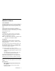
Checking the AC Adapter: You are here because the computer fails only when the AC Adapter is used: If the power-on indicator does not turn on, check the power cord of the AC Adapter for correct continuity and installation. If the operational charge does not work, go to “Checking the Operational Charging.” Unplug the AC Adapter cable from the computer and measure the output voltage at the plug of the AC Adapter cable. See the following figure. Pin Voltage (V dc) 1 +15.5 to +17.
Note: Signal lines, not used in these steps, are used for communications between the system and the battery. 3. If the voltage is less than 10.6V, the battery ASM has been discharged, recharge the battery ASM. If the voltage is still less than 10.6V, replace the battery. TrackPoint Checkout If the external mouse is connected, the TrackPoint does not work. In this case, please detach the external mouse to check the TrackPoint.
I/O Ports Checkout Note: Be sure to enable the serial and parallel ports in the BIOS setup utility before performing diagnostics tests on the I/O ports. Also, be sure to write down the I/O address for the serial port to identify the port in the diagnostic test. Do perform a diagnostics checkout on the I/O ports: 1. Boot from the diagnostics diskette and start the program. 2. Go to Diagnostics on the main menu and select Serial Ports or Parallel Ports.
The computer exits standby and resumes operation when any key is pressed. Suspend Mode: In suspend mode, the following occurs: The LCD is powered off. The hard disk drive is powered off. The CPU stops. Events that cause the computer to enter suspend mode: Suspend mode requested by the Fn key (Fn+F4). The Lid is closed. The specified time has elapsed. Battery low occurs and hibernation conditions are insufficient.
Timer conditions are satisfied in suspend mode when hibernate by timer is enabled. A critically low battery condition occurs. The power switch is pressed. (BIOS Setup) The computer exits hibernation mode and resumes operation when the power-on switch is pressed. When power is turned on, the hibernation file in the boot record on the hard disk drive is read and the system status is restored from the hard disk drive.
Symptom-to-FRU Index The Symptom-to-FRU Index lists the symptoms and errors and the possible causes. The most likely cause is listed first. Note: Perform the FRU replacement or actions in the sequence shown in the FRU/Action columns. If a FRU replacement does not solve the problem, put the original part back in the computer. Do not replace a non-defective FRU. This index can also be used to help you decide the next possible FRUs to be replaced when servicing a computer.
Symptom/Error FRU/Action in Sequence 0213 Unlock external keyboard. Keyboard locked — Unlock key switch 0220 Load Setup Defaults in BIOS Setup Utility. Monitor type does not match CMOS — Run Setup 0230 System board Shadow RAM Failed at offset:nnnn 0231 1. DIMM System RAM Failed at offset:nnnn 2. System board 0232 1. DIMM Extended RAM Failed at offset:nnnn 2.
Symptom/Error FRU/Action in Sequence 0281 1. Load Setup Defaults in the BIOS Setup Utility. Memory size found by POST differed from CMOS 02D0 2. DIMM 3. System board System board System cache error — Cache disabled 02F0 System board CPU ID: 02F5 1. DIMM DMA Test Failed 2. System board 02F6 1. DIMM Software NMI Failed 2. System board 02F7 1. DIMM Fail-Safe Timer NMI Failed 2. System board Error Messages Symptom/Error FRU/Action in Sequence Device Address Conflict 1.
No Beep Symptoms Symptom/Error No beep, power-on indicator on, LCD blank, no POST FRU/Action in Sequence Ensure every connector is connected tightly and correctly. DIMM System board No beep, power-on indicator off, LCD blank during POST Battery ASM AC Adapter System board No beep, power-on indicator on, LCD blank during POST Reseat DIMM. System board No beep during POST but system runs correctly.
Symptom/Error Indicator incorrectly remains off or on, but system runs correctly. FRU/Action in Sequence 1. Reseat the LED cable. 2. LED cable 3. System board Power-Related Symptoms Symptom/Error Power shuts down during operation. FRU/Action in Sequence 1. Battery 2. AC Adapter 3. System board The system will not power on. 1. Battery ASM 2. AC Adapter 3. System board The system will not power off. 1. System board Battery can't be charged.
Symptom/Error FRU/Action in Sequence The system will not enter suspend mode after closing the LCD. 1. LED Card ASM (R) Battery fuel-gauge does not go higher than 90%. 1. Remove battery ASM and let it cool for 2 hours. 2. System board 2. Refresh battery (continue using battery in BIOS Setup mode until power off, then charge battery). 3. Battery 4. System board System configuration does not match the installed devices. 1. Load Setup Defaults and reboot the system. System hangs intermittently. 1.
3. If any error is detected, replace the FRU shown by the FRU code. Rerun the test to verify that no more errors exist. Undetermined Problems You are here because the diagnostic tests did not identify which adapter or device failed, which installed devices are incorrect, whether a short circuit is suspected, or whether the system is inoperative. Follow these procedures to isolate the failing FRU (do not isolate non-defective FRUs).
CE Utility Program Diskette Writing the VPD Data The EEPROM on the system board contains the Vital Product Data (VPD) — that is, a computer serial number and a system board serial number. When you replace the system board, restore the computer serial number using the VPD Data Utility in the ThinkPad CE Utility Diskette. The serial number label is attached to the computer. Flash UUID The EEPROM on the system board contains the Universal Unique ID (UUID) — that is, for Microsoft or Internet use.
FRU Removals and Replacements This section contains information about removals and replacements. Do not damage any parts. Only certified and trained personnel should service the computer. The arrows in this section show the direction of movement to remove a FRU, or to turn a screw to release the FRU. The arrows are marked in numeric order, in square callouts, to show the correct sequence of removal.
LCD FRU Replacement Notice: The TFT LCD for the notebook computer contains over 2,359,296 thinfilm transistors (TFTs). A small number of missing, discolored, or lighted dots (on all the time) is characteristic of TFT LCD technology, but excessive pixel problems can cause viewing concerns. The LCD should be replaced if the number of missing, discolored, or lighted dots in any background is 8 or more.
1010 Battery ASM To remove the battery ASM: 1. Slide the release lock as shown. 2 1 2 1 2. Slide the release latch as shown. 3. Remove the battery ASM. Reverse the steps described above when installing a new battery pack.
1020 Hard Disk Drive Warning Do not drop or apply any shock to the hard disk drive. The hard disk drive is sensitive to physical shock. Incorrect handling can cause damage and permanent loss of data on the drive. Before removing the drive, have the user make a backup copy of all the information on the drive if possible. Never remove the drive while the system is operating or is in suspend mode. To remove the hard disk drive: 1. Remove the two screws from the hard disk cover. 2.
1030 Keyboard 1010 Battery ASM To remove the keyboard: 1. Remove the three screws securing the keyboard. Thin kPa d 2. Turn the notebook over; then lift the keyboard as shown. 3. Remove the keyboard stopper sheet screw. 4. Disconnect the keyboard connector from the system board. Remove the keyboard from the lower case.
Thin kPad Step Size (Quantity) Head & Color 1 M2.0 x 9L (3) Flat head, black 2.5 kgf-cm 3 M2.5 x 6L (1) Flat head, silver 2.5 kgf-cm Torque Note: Make sure you use the correct screw for replacement.
1040 Modem Card 1010 Battery ASM 1030 Keyboard To remove the modem card: Thin kPad 1. Carefully release the latches on both sides of the modem card. 2. Disconnect the modem cable from the connector. 3. Gently remove the modem card.
1050 DIMM Card 1010 Battery ASM 1030 Keyboard To remove the memory card: Thin kPad 1. Carefully release the latches on both sides of the memory card. 2. Gently remove the memory card.
1060 LCD Unit ASM Note: Refer to “ThinkPad 240 Hardware Maintenance Manual” on page 1 for information on LCD Type A and LCD Type B panel designations. 1010 Battery ASM 1030 Keyboard Note: The Cu tape must be reseated firmly after the LCD unit ASM is replaced .3/. To remove the LCD unit ASM: 1. Remove the screws as shown. 2 1 2. Turn the notebook over; then remove the hinge covers. 3. Remove the Cu tape from the FPC cable. 4. Disconnect the LCD FPC cable from the system board. 5.
Step Size (Quantity) Head & Color 1 M2.0 x 4L (2) Flat head, black 2.5 kgf–cm 5 M2.5 x 6 L (4) Flat head, silver 3.5 kgf-cm Torque Note: Make sure you use the correct screw for replacement.
1070 Upper Cover ASM 1010 Battery ASM 1020 Hard Disk Drive 1030 Keyboard 1060 LCD Unit ASM To remove the upper cover ASM: 1. Remove the screw cover. 2. Remove the screw. 3. Remove the other screw as shown. Step Size (Quantity) Head & Color 2 M2.0 x 4L (1) Flat head, black 2.5 kgf-cm 3 M2.5 x 7L (1) Flat head, black 2.5 kgf-cm 4 M2.0 x 4L Flat head, black 2.0 kgf-cm Torque Note: Make sure you use the correct screw for replacement. 4.
5. Disconnect the Touchbutton cable from the system board. 6. Carefully lift the upper cover to expose the speaker connector as shown. 7. Disconnect the speaker cable from the main unit. Now you can remove the upper cover ASM from the base cover ASM.
1080 Speaker ASM 1010 Battery ASM 1020 Hard Disk Drive 1030 Keyboard 1060 LCD Unit ASM 1070 Upper Cover ASM To remove the speaker: 1. Remove the three screws securing the speaker. 2. Remove the securing tape from the cable. 3. Gently lift the speaker away from the upper cover. Step Size (Quantity) Head & Color 1 M2.0 x 3L (3) Flat head, silver Torque 2.5 kgf-cm Note: Make sure you use the correct screw for replacement.
1085 Select Button ASM 1010 Battery ASM 1020 Hard Disk Drive 1030 Keyboard 1060 LCD Unit ASM 1070 Upper Cover ASM To remove the select button ASM: 1. Remove the three screws as shown. 2. Remove the select button ASM from the top cover ASM. Step 1 Size (Quantity) Head & Color M2.5 x 2.5L (3) Flat head, silver Torque 2.0 kgf-cm Note: Make sure you use the correct screw for replacement.
1090 Cable ASM and Cable ASM LED-R 1010 Battery ASM 1020 Hard Disk Drive 1030 Keyboard 1060 LCD Unit ASM 1070 Upper Cover ASM To remove the hinge LED cable: 1. Disconnect the LED cable, then lift it as shown. (The cable is fixed with double-sided tape.) To remove the cable ASM LED-R: 1. Remove the screw. 2. Disconnect the LED board, then lift it as shown. Step Size (Quantity) Head & Color 1 M2.0 x 7L (1) Flat head, silver Torque 2.
1100 Fan ASM 1010 Battery ASM 1020 Hard Disk Drive 1030 Keyboard 1060 LCD Unit ASM 1070 Upper Cover ASM 1090 Cable ASM and Cable ASM LED-R Warning Do not apply pressure on the fan blades or hub assembly; doing so can damage the fan bearings. To remove the fan ASM: 1. Remove the two screws securing the fan ASM. 2. Carefully lift the fan ASM. 3. Disconnect the cable from the system board.
Step Size (Quantity) Head & Color Torque Note: Make sure you use the correct screw for replacement.
1110 Modem Cable ASM 1010 Battery ASM 1020 Hard Disk Drive 1030 Keyboard 1060 LCD Unit ASM 1070 Upper Cover ASM To remove the modem cable ASM: Disconnect the modem cable from the system board. Remove the cable as shown.
1120 Water Channel ASM 1010 Battery ASM 1020 Hard Disk Drive 1030 Keyboard 1060 LCD Unit ASM 1070 Upper Cover ASM To remove the water channel ASM: 42 Remove the water channel ASM as shown.
1130 System Board 1010 Battery ASM 1020 Hard Disk Drive 1030 Keyboard 1060 LCD Unit ASM 1070 Upper Cover ASM 1090 Cable ASM and Cable ASM LED-R 1100 Fan ASM 1120 Water Channel ASM Note: See “Replacing the System Board” on page 25 before proceeding. 1. Remove the screws as shown. 2. Turn the notebook over; remove the two screws from the diskette drive connector. 3. Remove the screw from the PCMCIA slot. 4. Remove the battery terminal screw. 5.
6. Remove the system board from the base cover ASM. Step Size (Quantity) Head & Color 1 M2.0 x 4L (5) Flat head, black 2.5 kgf-cm 2 M2.0 x 6L (2) Flat head, black 2.0 kgf-cm 3 M2.0 x 4L (1) Flat head, black 2.0 kgf-cm 4 M2.0 x 8L (1) Flat head, black 2.0 kgf-cm Torque Note: Make sure you use the correct screw for replacement.
1135 Rear Bracket 1010 Battery ASM 1020 Hard Disk Drive 1030 Keyboard 1060 LCD Unit ASM 1070 Upper Cover ASM 1090 Cable ASM and Cable ASM LED-R 1100 Fan ASM 1120 Water Channel ASM 1130 System Board Note: See “Replacing the System Board” on page 25 before proceeding. 1. Remove the six hexagonal studs as shown. 2. Remove the microphone. 3. Remove the rear bracket. Step 1 Size (Quantity) Head & Color M2.5 x 4.5L (6) Hex head, silver Torque 4.
1140 PCMCIA Slots 1010 Battery ASM 1020 Hard Disk Drive 1030 Keyboard 1060 LCD Unit ASM 1070 Upper Cover ASM 1090 Cable ASM and Cable ASM LED-R 1100 Fan ASM 1120 Water Channel ASM 1130 System Board Warning Special care must be taken when disconnecting the PCMCIA card not to cause a short or damage the connector. To remove the PCMCIA slots: 1. Remove the screw securing the PCMCIA slot board. 2.
1150 LCD Bezel ASM 1010 Battery ASM 1. Remove the screw cap covers. 2. Remove the screws as shown. Thin kPad A 3. Gripping as shown, remove the LCD bezel. Thin kPad 4. The LCD latches must be opened as shown to remove the bezel. 5. Remove the bezel from the LCD unit. Step Size (Quantity) Head & Color 2 M2.5 x 5L (2) Flat head, black 2.5 kgf-cm 2A M2.5 x 5L (2) Flat head, black 1.5 kgf-cm Torque Note: Make sure you use the correct screw for replacement.
1160 LCD Inverter ASM 1010 Battery ASM 1150 LCD Bezel ASM To remove the LCD inverter ASM: 1. Disconnect the flex cable from the inverter card. ThinkP ad 2. Disconnect the FPC cable from the inverter card. 3. Remove the inverter card. (The inverter card is fixed to the rear cover with double-sided tape.
1170 LCD Panel ASM (LCD Type A and B) Note: Refer to “ThinkPad 240 Hardware Maintenance Manual” on page 1 for information on LCD Type A and LCD Type B panel designations. 1010 Battery ASM 1030 Keyboard 1150 LCD Bezel ASM 1160 LCD Inverter ASM To remove the LCD Panel: 1. Remove the screws as shown. 2 1 2. Turn the notebook over; remove the CU tape and disconnect the FPC cable. Thi nkP ad 3. Remove the four screws securing the LCD Panel. 4.
5. Remove the LCD panel. Step Size (Quantity) Head & Color 1 M2.0 x 4L (2) Flat head, black 2.5 kgf–cm 3 (LCD Type A) M2.5 x 4L (4) Flat head, silver 3.0 kgf–cm 3 (LCD Type B) M2.0 x 4L (4) Flat head, silver 3.0 kgf–cm Torque Note: Make sure you use the correct screw for replacement.
1180 LCD FPC ASM (LCD Type A) Note: Refer to “ThinkPad 240 Hardware Maintenance Manual” on page 1 for information on LCD Type A and LCD Type B panel designations. 1010 Battery ASM 1030 Keyboard 1150 LCD Bezel ASM 1160 LCD Inverter ASM 1170 LCD Panel ASM (LCD Type A and B) Note: When replacing the flex cable in the following procedure, the labelled face of the cable must face away from the LCD panel. 1. Remove the tape from the FPC cable. 2.
1185 LCD FPC ASM (LCD Type B) Note: Refer to “ThinkPad 240 Hardware Maintenance Manual” on page 1 for information on LCD Type A and LCD Type B panel designations. 1010 Battery ASM 1030 Keyboard 1150 LCD Bezel ASM 1160 LCD Inverter ASM 1170 LCD Panel ASM (LCD Type A and B) 1. Remove the tape from the FPC cable. 2. Open the fasteners on the FPC cable holder. 3. Disconnect the FPC connector from the LCD panel.
1190 Hinge ASM 1010 Battery ASM 1030 Keyboard 1060 LCD Unit ASM 1150 LCD Bezel ASM 1. Remove the screws as shown. 2. Remove the hinge ASM. Step Size (Quantity) Head & Color 1 M2.5 x 4L (2) Flat head, silver Torque 3.5 kgf–cm Note: Make sure you use the correct screw for replacement.
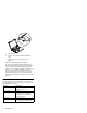
Computer Parts Listing d a b c Index Description FRU Number a— d See MISC PARTS list 10L1955 1 HINGE CAP L/R 10L1954 2 UPPER COVER ASM 10L1944 3 REAR BRACKET 10L1952 4 LED CARD ASM (L) 10L1303 5 SERIAL/VGA CAP 10L1951 6 STD BATTERY PACK 02K6606 7 PCMCIA SLOT 10L1945 8 DISKETTE DRIVE CONNECTOR LID 10L1953 9 TRACKPOINT CAP 84G6536 10 See Keyboard list 11 SELECT BUTTON ASM 54 ThinkPad 240 10L1958
Index Description FRU Number 12 FAN ASM 10L1957 13 SPEAKER ASM 02K6307 14 LED CARD ASM (R) 10L1304 15 SYSTEM BOARD ASM 32 MB (Model 1) 10L1302 15 SYSTEM BOARD ASM 64 MB (Model 2) 30L2766 15 SYSTEM BOARD ASM 64 MB (Model 3) 08K3426 15 SYSTEM BOARD ASM 64 MB (Model 4) 08K3143 16 MODEM CARD ASM 10L1305 17 BASE COVER ASM 10L1946 BASE COVER ASM PRC 10L1948 BASE COVER ASM Korea 10L1949 HARD DISK DRIVE ASM 3.2 GB (Model 1) 05K9117 HARD DISK DRIVE ASM 6.
Description FRU Number TELEPHONE CABLE UK 27L0480 TELEPHONE CABLE Germany 27L0481 TELEPHONE CABLE France 27L0482 32 MB DIMM 42H2819 64 MB DIMM 10L1313 128 MB DIMM 01K1153 EXTERNAL DISKETTE DRIVE CABLE 12J1711 EXTERNAL DISKETTE DRIVE ASM 05K8989 05K8990 LARGE BATTERY 02K6607 MISC PARTS 10L1955 (a) MODEM DOOR (b) SHUTTER (PCMCIA) (c) SPRING SHUTTER (d) WATER CHANNEL (e) FPC HOLDER (upper) (f) FPC HOLDER (lower) (g) HOOK KNOB - R (h) SPRING HOOK - R (i) HOOK KNOB - L (j) SPRING-HOOK - L O
Description FRU Number Power cord (Abu Dhabi, Albania, Antigua, Bahrain, Brunei, Dubai, Fiji, Hong Kong, India, Ireland, Kenya, Kuwait, Macao, Malaysia, Nigeria, Oman, People's Republic of China, Qatar, Singapore, United Kingdom) 76H3524 Power cord (Switzerland) 76H3528 Power cord (Israel) 76H3532 Power cord (Chile, Italy) 76H3530 Power cord (Korea) 76H3535 Power cord (PRC) 02K0539 ThinkPad 240 57
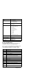
LCD Unit Parts Listing (LCD Type A) j i h e g f Note: Refer to “ThinkPad 240 Hardware Maintenance Manual” on page 1 for information on LCD Type A and LCD Type B panel designations. Index Computer FRU Number e—j See MISC PARTS list 10L1955 1 LCD BEZEL ASM 10L1941 LCD BEZEL ASM Korea 10L1942 2 LCD UNIT-TFT 10.
LCD Unit Parts Listing (LCD Type B) j i h e g f Note: Refer to “ThinkPad 240 Hardware Maintenance Manual” on page 1 for information on LCD Type A and LCD Type B panel designations. Index Computer FRU Number e—j See MISC PARTS list 10L1955 1 LCD BEZEL ASM 10L1941 LCD BEZEL ASM Korea 10L1942 2 LCD UNIT-TFT 10.
Description FRU No.
Notices References in this publication to IBM products, programs, or services do not imply that IBM intends to make these available in all countries in which IBM operates. Any reference to an IBM product, program, or service is not intended to state or imply that only IBM product, program, or service may be used.
IBM Part Number: 09N8590 Printed in U.S.A.