ThinkCentre™ Hardware Removal and Replacement Guide Types 8424, 8425, 8428 Types 8171, 8172, 8173
ThinkCentre™ Hardware Removal and Replacement Guide Types 8424, 8425, 8428 Types 8171, 8172, 8173
Second Edition (June 2004) © Copyright International Business Machines Corporation 2004. All rights reserved. US Government Users Restricted Rights – Use, duplication or disclosure restricted by GSA ADP Schedule Contract with IBM Corp.
Contents Overview . . . . . . . . . . . . . . v Safety information . . . . . Additional information resources Tools required . . . . . . . Handling static-sensitive devices . . . . . . . . . . . . . . . . . . . . . . . . . . . . v v v v Replacing customer replaceable units (CRUs) . . . . . . . . . . . . . . . 1 Opening the cover . . © Copyright IBM Corp. 2004 . . . . . . . . . . 1 Locating components . . . . . . . . . . . 2 Identifying parts on the system board . . . . . .
iv Hardware Removal and Replacement Guide
Overview This guide contains instructions for replacing the following customer replacement units (CRUs): v Power supply v System board v Microprocessor v Hard disk drive v Memory modules Safety information Do not open your computer or attempt any repair before reading the “Important safety information” in the Quick Reference that was included with your computer. If you no longer have this copy of the Quick Reference, you can obtain one online from the IBM Web site at http://www.ibm.com/pc/support.
v Before you replace a new CRU, touch the static-protective package containing the CRU to a metal expansion-slot cover or other unpainted metal surface on the computer for at least two seconds. This reduces static electricity in the package and your body. v When possible, remove the new CRU from the static-protective packaging, and install it directly in the computer without setting the CRU down.
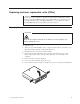
Replacing customer replaceable units (CRUs) Attention Do not open your computer or attempt any repair before reading the “Safety notices” in the Quick Reference that was included with your computer. If you no longer have this copy of the Quick Reference, you can obtain one online from the IBM Web site at http://www.ibm.com/pc/support. Opening the cover Important Turn off the computer and wait 3 to 5 minutes to let the computer cool before opening the cover. To open the cover: 1.
Locating components The following illustration will help you locate the various components in your computer.
Identifying parts on the system board The system board (sometimes called the planar or motherboard) is the main circuit board in your computer. It provides basic computer functions and supports a variety of devices. The following illustration shows the locations of parts on the system board.
2. Pivot the drive bay assembly upward to gain access to the cable connections. 3. Locate the power supply. See “Locating components” on page 2. Note: Note the routing of the power supply cables. It is important to route the cables the same way when installing a new power supply assembly. 4. Disconnect the power cables from the hard disk drive and the CD-ROM drive. 5. Disconnect the power cables P1 1 and P2 2 from the system board. 6.
7. Remove the screws at the rear of the chassis that secure the power supply. 8. Slide the power supply forward and remove from the computer.
9. Install the new power supply into the chassis so that the screw holes in the power supply align with those in the chassis. Note: Use only the screws provided by IBM. 10. Install and tighten the four screws at the rear of the chassis that secure the power supply. 11. Reconnect the speaker wire to the system board. 12. Reconnect power supply connectors to the system board. 13. Reconnect power supply connectors to the hard disk drive and CD-ROM drive, as required. 14.
Removing and replacing the system board assembly Attention Do not open your computer or attempt any repair before reading the “Safety notices” in the Quick Reference that was included with your computer. If you no longer have this copy of the Quick Reference, you can obtain one online from the IBM Web site at http://www.ibm.com/pc/support. To remove and replace the system board assembly, do the following: 1. Turn off the computer and allow the computer to cool for one hour. 2. Open the cover.
installed. 5. Carefully note the location of all cable connections on the system board. It will be necessary to reconnect them properly after installing the new system board assembly. Note: Note the cable routing. It is important to route the cables the same way when installing a new system board. 6. Disconnect the diskette drive cable from the system board by sliding the plastic cable retainer upward to release the cable. 7. Disconnect all other cables connected to the system board.
10. Using the two blue handles provided, lift the system board assembly out of the computer. 11. Place the old system board next to the new system board on a clean, flat surface. 12. Remove the microprocessor from the old system board. Go to “Removing and replacing the microprocessor” on page 10. Return here after removing the microprocessor. 13. Remove all memory modules from the old system board, and install them on the new system board. Go to “Removing and replacing memory modules” on page 15.
Removing and replacing the microprocessor Attention Do not open your computer or attempt any repair before reading the “Safety notices” in the Quick Reference that was included with your computer. If you no longer have this copy of the Quick Reference, you can obtain one online from the IBM Web site at http://www.ibm.com/pc/support.
4. Release the lever 1 holding the microprocessor heat sink. 5. Remove the heat sink, and do one of the following: v If you are replacing the microprocessor, place the old heat sink aside. You must use the new heat sink shipped with the new microprocessor. Note Do not use the old heat sink with the a new microprocessor. If you use the old heat sink with the new microprocessor, your computer might overheat causing intermittent problems.
* X X X X X X X X X * Notes: a. Notice of the orientation of the notches 1 on the microprocessor . This is important when reinstalling the microprocessor on the system board. b. Do not drop anything on the socket while it is open. Keep all contacts as clean as possible. 7. To install the microprocessor, do one of the following: Attention To avoid damaging the microprocessor pins, do not tilt the microprocessor when installing it into the microprocessor socket.
* X X X X X X X X X * b. Remove the new microprocessor from its static-protective package. c. Hold the microprocessor 2 by its sides and loosen the black cover 3 on the microprocessor, but do not remove the black cover. d. Place the microprocessor on the static-protective package. e. Use the vacuum pen 1 to pick up the new microprocessor, and remove the black cover. f. Place the black cover on the old microprocessor to protect the gold contacts. g.
b. Install the microprocessor by inserting it straight down into the socket of the new system board. 8. Pivot the retaining plate 1 closed, and lock the lever 3 to secure the microprocessor 2 in place. Be sure to engage the retainer tab when locking the microprocessor. * XXXXXXXXX* 9. Do one of the following: v If you have replaced the microprocessor, place the new heat sink on the microprocessor, and lower the lever into the locked position.
Removing and replacing memory modules Attention Do not open your computer or attempt any repair before reading the “Safety notices” in the Quick Reference that was included with your computer. If you no longer have this copy of the Quick Reference, you can obtain one online from the IBM Web site at http://www.ibm.com/pc/support. To remove and replace the memory modules: 1. Open the cover. Go to “Opening the cover” on page 1. 2. Pivot the drive bay assembly upward to gain access to the system board. 3.
installed. 4. Locate the memory connectors. See “Locating components” on page 2. 5. Open the retaining clips, and lift the memory module out of its connector. 6. Insert the replacement memory module in the memory connector. Ensure the notch on the replacement memory module 1 aligns correctly with the connector key 2 on the system board. Push the memory module straight down into the connector until the retaining clips close.
7. Reinstall the PCI riser and adapters if they were removed. 8. Pivot the drive bay assembly back to the original position. 9. Close the cover and reconnect the external cables . Go to “Completing the installation” on page 19.
Removing and replacing a hard disk drive Attention Do not open your computer or attempt any repair before reading the “Safety notices” in the Quick Reference that was included with your computer. If you no longer have this copy of the Quick Reference, you can obtain one online from the IBM Web site at http://www.ibm.com/pc/support. 1. Open the cover. Go to “Opening the cover” on page 1. 2. Pivot the drive bay assembly upward to gain access to the cable connections. 3.
6. Remove the old hard disk drive from the blue bracket by flexing the bracket. Do not touch the circuits 5 on the hard disk drive. 7. Insert the new hard disk drive into the blue bracket aligning the pins 1 through 4 on the bracket with the holes in the hard disk drive. 8. Insert the hard disk drive into hard disk bay with the circuits facing up and snap it into position. 9. Connect a power connector to the drive. 10. Reconnect the CD drive cable. 11.
Attention Keep cables 1 through 3 clear of the hinges and sides of the computer chassis. 3. Make sure that the drive locks on the drive bay assembly are both in the locked position. Otherwise, you cannot close the cover. 4. Close the cover. 5. If a cover lock is installed, lock the cover. 6. If your computer is being placed in the vertical position, attach the floor stand.
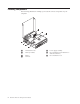
7. Reconnect the external cables. Plug the power cord into the computer then into a properly grounded power receptacle. 1 2 3 4 5 6 7 8 Power cord connector 9 Cable lock latch 10 Rope clip (U-bolt) holes 11 PCI and PCI express adapter slots 12 Serial connectors (2) 13 Ethernet connector 14 USB connectors (2) 15 VGA monitor connector Parallel connector Audio line-in connector Audio line-out connector USB connectors (4) PS/2 keyboard connector PS/2 mouse connector LEDs 8.
3. When you are prompted to select a language, press the number on your keyboard which corresponds to the language then press Enter. 4. When prompted to change the serial number, press Y. 5. Type in the seven character serial number of your computer then press Enter. 6. When prompted to change the machine type/model, press Y. 7. Type in the seven character machine type/model of your computer then press Enter. 8. Follow the instructions on the screen to complete the update.
Part Number: 19R0821 Printed in USA (1P) P/N: 19R0821