
Personal Computer User Manual
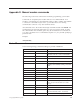
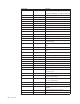
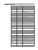
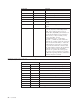
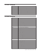
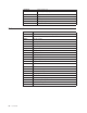
Table Of Contents
- Contents
- Important safety information
- Chapter 1. Overview
- Chapter 2. Installing options
- Handling static-sensitive devices
- Installing external options
- Opening the cover
- Locating components
- Accessing system board components and drives
- Identifying parts on the system board
- Installing memory
- Installing PCI adapters
- Installing internal drives
- Installing security features
- Erasing a lost or forgotten password (clearing CMOS)
- Closing the cover and connecting the cables
- Chapter 3. Using the IBM Setup Utility
- Appendix A. Replacing customer replaceable units (CRU)
- CRU list
- Removing and replacing the power supply assembly
- Removing and replacing the system board assembly
- Removing the microprocessor
- Replacing the microprocessor
- Removing and replacing the battery
- Removing and replacing the speaker
- Removing and replacing the power button and LED assembly
- Removing and replacing the fan assembly
- Completing the installation
- Appendix B. Updating POST/BIOS
- Appendix C. Cleaning the mouse
- Appendix D. Manual modem commands
- Appendix E. Notices
- Index

Extended
AT
commands
Command
Function
&C_
&C0
Force
Carrier
Detect
Signal
High
(ON)
&C1
Turn
on
CD
when
remote
carrier
is
present
&D_
&D0
Modem
ignores
the
DTR
signal
&D1
Modem
returns
to
Command
Mode
after
DTR
toggle
&D2
Modem
hangs
up,
returns
to
the
Command
Mode
after
DTR
toggle
&D3
Resets
modem
after
DTR
toggle
&F_
&F
Recall
factory
default
configuration
&G_
&G0
Guard
tone
disabled
&G1
Guard
tone
disabled
&G2
1800
Hz
guard
tone
&K_
&K0
Disable
flow
control
&K3
Enable
RTS/CTS
hardware
flow
control
&K4
Enable
XON/XOFF
software
flow
control
&K5
Enable
transparent
XON/XOFF
flow
control
&K6
Enable
both
RTS/CTS
and
XON/XOFF
flow
control
&M_
&M0
Asynchronous
operation
&P_
&P0
US
setting
for
off-hook-to-on-hook
ratio
&P1
UK
and
Hong
Kong
off-hook-to-on-hook
ratio
&P2
Same
as
&P0
setting
but
at
20
pulses
per
minute
&P3
Same
as
&P1
setting
but
at
20
pulses
per
minute
&R_
&R0
Reserved
&R1
CTS
operates
per
flow
control
requirements
&S_
&S0
Force
DSR
Signal
High
(ON)
&S1
DSR
off
in
command
mode,
on
in
on-line
mode
&T_
&T0
Ends
test
in
progress
&T1
Perform
Local
Analog
Loopback
Test
&T3
Perform
Local
Digital
Loopback
Test
&T4
Grant
Remote
Digital
Loopback
Test
request
by
remote
modem
&T5
Deny
Remote
Digital
Loopback
Test
request
&T6
Perform
a
Remote
Digital
Loopback
Test
&T7
Perform
a
Remote
Digital
Loopback
Test
and
Self-Test
&T8
Perform
Local
Analog
Loopback
Test
and
Self-Test
&V
&V0
Displays
Active
and
Stored
Profiles
Appendix
D.
Manual
modem
commands
53