ThinkCentre™ User Guide Types 8183, 8184, 8320, 8416 Types 8417, 8418, 8419, 8429
ThinkCentre™ User Guide Types 8183, 8184, 8320, 8416 Types 8417, 8418, 8419, 8429
Note Before using this information and the product it supports, be sure to read the “Important safety information” on page v and Appendix E, “Notices,” on page 59. Fourth Edition (October 2003) © Copyright International Business Machines Corporation 2003. All rights reserved. US Government Users Restricted Rights – Use, duplication or disclosure restricted by GSA ADP Schedule Contract with IBM Corp.
Contents Important safety information . . . . . . v Conditions that require immediate action . . . . . v General safety guidelines . . . . . . . . . . vi Service . . . . . . . . . . . . . . . vi Power cords and power adapters . . . . . . vi Extension cords and related devices . . . . . vii Plugs and outlets . . . . . . . . . . . vii Batteries . . . . . . . . . . . . . . vii Heat and product ventilation . . . . . . . viii CD and DVD drive safety . . . . . . . . viii Additional safety information . . . . . .
iv User Guide
Important safety information This information can help you safely use your IBM® personal computer. Follow and retain all information included with your IBM computer. The information in this document does not alter the terms of your purchase agreement or the IBM Statement of Limited Warranty. Customer safety is important to IBM. Our products are developed to be safe and effective. However, personal computers are electronic devices.
v Damage to a battery (such as cracks, dents, creases), discharge from a battery, or a buildup of foreign substances on the battery. v A cracking, hissing or popping sound, or strong odor that comes from the product. v Signs that liquid has been spilled or an object has fallen onto the computer product, the power cord or power adapter. v The computer product, the power cord or power adapter has been exposed to water. v The product has been dropped or damaged in any way.
Do not use any power adapter that shows corrosion at the ac input pins and/or shows signs of overheating (such as deformed plastic) at the ac input or anywhere on the power adapter. Do not use any power cords where the electrical contacts on either end show signs of corrosion or overheating or where the power cord appears to have been damaged in any way.
foreign materials on the battery leads, stop using the battery and obtain a replacement from the battery manufacturer. Batteries can degrade when they are left unused for long periods of time. For some rechargeable batteries (particularly Lithium Ion batteries), leaving a battery unused in a discharged state could increase the risk of a battery short circuit, which could shorten the life of the battery and can also pose a safety hazard.
v Connect to properly wired outlets any equipment that will be attached to this product. v When possible, use one hand only to connect or disconnect signal cables. v Never turn on any equipment when there is evidence of fire, water, or structural damage. v Disconnect the attached power cords, telecommunications systems, networks, and modems before you open the device covers, unless instructed otherwise in the installation and configuration procedures.
Lithium battery notice CAUTION: Danger of explosion if battery is incorrectly replaced. When replacing the battery, use only IBM Part Number 33F8354 or an equivalent type battery recommended by the manufacturer. The battery contains lithium and can explode if not properly used, handled, or disposed of. Do not: v Throw or immerse into water v Heat to more than 100°C (212°F) v Repair or disassemble Dispose of the battery as required by local ordinances or regulations.
v Les prises téléphoniques ne doivent pas être installées dans des endroits humides, excepté si le modèle a été conçu à cet effet. v Ne touchez jamais un cordon téléphonique ou un terminal non isolé avant que la ligne ait été déconnectée du réseau téléphonique. v Soyez toujours prudent lorsque vous procédez à l’installation ou à la modification de lignes téléphoniques. v Si vous devez téléphoner pendant un orage, pour éviter tout risque de choc électrique, utilisez toujours un téléphone sans fil.
ATTENTION: Pour éviter tout risque d’exposition au rayon laser, respectez les consignes de réglage et d’utilisation des commandes, ainsi que les procédures décrites. L’ouverture de l’unité de CD-ROM/DVD-ROM peut entraîner un risque d’exposition au rayon laser. Pour toute intervention, faites appel à du personnel qualifié. Certaines unités de CD-ROM/DVD-ROM peuvent contenir une diode à laser de classe 3A ou 3B. Tenez compte de la consigne qui suit: DANGER Rayonnement laser lorsque le carter est ouvert.
Chapter 1. Overview Thank you for selecting an IBM® computer. Your computer incorporates many of the latest advances in computer technology and can be upgraded as your needs change. Instructions for installing external and internal options are included in this publication. When adding an option, use these instructions along with the instructions that come along with the option.
Features This section provides an overview of the computer features and preinstalled software. System summary The following information covers a variety of models. For a listing of features for your specific model, go to Chapter 3, “Using the IBM Setup Utility,” on page 27. Microprocessor v Intel Pentium® 4 processor with HyperThreading v Intel Pentium 4 processor v Intel® Celeron™ processor v Internal cache (size varies by model type) Memory Support for two 184-pin dual inline memory modules (DIMMs).
v Automatic power-on startup v System Management (SM) BIOS and SM software v Ability to store POST hardware test results Input/output features v 25-pin, Extended Capabilities Port (ECP)/Extended Parallel Port (EPP) v Two 9-pin serial connectors v Eight USB 2.
Operating systems (preinstalled) (varies by model) Note: Not all countries or regions will have these operating systems.
Specifications This section lists certain specifications for your computer. For the latest specification information, see the User Guide for your computer model and type at: http://www.ibm.com/pc/support/ Dimensions Width: 12.2 inches (310 mm) Height: 3.35 inches (85 mm) Depth: 14.1 inches (358 mm) Weight Minimum configuration as shipped: 8.2 kg (18 lbs) Environment Airflow for computers with a microprocessor that runs at or below 2.8 GHz Approximately 13 cubic feet (0.
Supported operating positions To provide proper air flow to internal components, you must position your computer in one of the positions as illustrated below.
Chapter 2. Installing options This chapter provides instructions for installing optional memory, PCI adapters, drives, and security features. When installing an option, use these instructions along with the instructions that come with the option. Use these procedures also if you are replacing any of these options as a customer replaceable unit (CRU). See Appendix A, “Replacing customer replaceable units (CRU),” on page 31 for other CRUs.
Locating controls and connectors on the front of your computer The following illustration shows locations of the controls and connectors on the front of your computer.
Locating connectors on the rear of your computer The following illustration shows locations of connectors on the rear of your computer.
Opening the cover Important Read “Important safety information” on page v and “Handling static-sensitive devices” on page 7 before opening the cover. To open the cover: 1. Shut down your operating system, remove any media (diskettes, CDs, or tapes) from the drives, and turn off all attached devices and the computer. 2. Unplug all power cords from electrical outlets. 3. Disconnect all cables attached to the computer.
Locating components The following illustration will help you locate the various components in your computer. 1 2 Diskette drive lock DIMM (memory) connectors (2) 5 6 3 4 Battery PCI riser 7 Power supply assembly CD or DVD drive (hard disk drive is under the CD drive) CD or DVD drive lock Chapter 2.
Accessing system board components and drives You might need to rotate the drive bay assembly upward and remove the PCI riser and adapters to access system board components such as memory, the battery, the Clear CMOS/BIOS recovery jumper and to access the drives. To 1. 2. 3. access system board components and the drives: Turn off the computer. Open the cover. See “Opening the cover” on page 10. Rotate the drive bay assembly upward as illustrated.
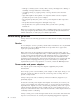
Identifying parts on the system board The system board (sometimes called the planar or motherboard) is the main circuit board in your computer. It provides basic computer functions and supports a variety of devices that are IBM-installed or that you can install later. The following illustration shows the locations of parts on the system board.
Installing memory Your computer has two connectors for installing dual inline memory modules (DIMMs) that provide up to a maximum of 2 GB of system memory. When installing memory, the following rules apply: v Use 2.5 V, 184-pin, double data rate synchronous dynamic random access memory (DDR SDRAM), non-ECC DIMMs. v Use 128 MB, 256 MB, 512 MB, or 1 GB DIMMs (when available) in any combination. Note: Only DDR SDRAM DIMMs can be used. To install DIMMs: 1. Access the system board.
Installing PCI adapters This section provides information and instructions for installing and removing PCI adapters. Your computer has a riser card with two PCI expansion slots. To install a PCI adapter: 1. Open the cover. See “Opening the cover” on page 10. 2. While holding the left rear of the computer chassis down, pull upward on the handle provided, to remove the PCI riser and any adapters that are currently installed. 3.
6. Position the adapter-slot-cover latch to retain the adapters. 7. Reinstall the PCI riser and adapters. 8. Close the cover. See “Closing the cover and connecting the cables” on page 25. What to do next: v To work with another option, go to the appropriate section. v To complete the installation, go to “Closing the cover and connecting the cables” on page 25. Installing internal drives This section provides information and instructions for removing and installing internal drives.
Parallel ATA IDE drive Serial ATA IDE drive Listed below are the various types of drives and the connector used to connect them to the system board. Each drive also requires the connection of a power cable from the power supply.
Removing and replacing a CD-ROM, CD-RW, or DVD optical drive 1. Open the cover. See “Opening the cover” on page 10. 2. Rotate the drive bay assembly upward to gain access to the cable connections. See “Accessing system board components and drives” on page 12 and “Locating components” on page 11. 3. Disconnect the signal and power cables from the drive. Note: Blue straps are provided to help when disconnecting cables. 4. Slide the lock 1 to the unlocked position. 5.
Removing and replacing a hard disk drive 1. Open the cover. See “Opening the cover” on page 10.. 2. Rotate the drive bay assembly upward to gain access to the cable connections. See “Accessing system board components and drives” on page 12 and “Locating components” on page 11. 3. If a CD drive is installed, it helps to disconnect the signal cable from the drive to access the hard disk drive cables. Note: Blue straps are provided to help when disconnecting cables. 4.
What to do next: v To work with another option, go to the appropriate section. v To complete the installation, go to “Closing the cover and connecting the cables” on page 25. Removing and replacing a diskette drive 1. Open the cover. See “Opening the cover” on page 10. 2. Slide the lock 1 to the unlocked position. 3. Slide the drive towards the rear of the computer far enough to gain access to the flat cable connector on the drive and disconnect the flat cable from the drive. 4.
Note: When replacing a parallel ATA with a serial ATA hard disk drive, you must obtain the signal cable. It is not included with your computer. 2. Locate the SATA connectors on the system board. See “Identifying parts on the system board” on page 13. 3. Connect one end of the signal cable to the drive and the other to either the SATA 1 IDE or the SATA 2 IDE connector on the system board. Note: It makes no difference which SATA connector you use. 4. Connect a power connector to the drive. 5.
Make sure that any security cables you install do not interfere with other computer cables. Identifying security locks The following illustration will help you to identify the various types of security locks that your computer might have.
® Chapter 2.
Rope clip Using a 3/16 in (5 mm) security rope clip (sometimes referred to as a U-bolt), a steel security cable, and a padlock you can secure your computer to a desk, table, or other non-permanent fixture. For computers designed to accommodate the rope clip, knockouts at the rear of the chassis are provided. To 1. 2. 3. install a rope clip: Remove the cover. See “Opening the cover” on page 10. Use a tool, such as a screwdriver, to remove the two metal knockouts.
Erasing a lost or forgotten password (clearing CMOS) This section applies to lost or forgotten passwords. For more information about lost or forgotten passwords, go to Access IBM. Note: Some models have a POV daughter card installed on the system board. In these models, the password is stored in the EEPROM on the POV card and cannot be erased. See “Identifying parts on the system board” on page 13 for the location of the POV card. To erase a forgotten password: 1.
26 User Guide
Chapter 3. Using the IBM Setup Utility The IBM Setup Utility program is stored in the electrically erasable programmable read-only memory (EEPROM) of your computer. The IBM Setup Utility program is used to view and change the configuration settings of your computer, regardless of which operating system you are using. However, the operating-system settings might override any similar settings in the IBM Setup Utility program. Starting the IBM Setup Utility program To 1. 2. 3. 4.
Exiting from the IBM Setup Utility program When you finish viewing or changing settings, press Esc to return to the IBM Setup Utility program menu (you might have to press Esc several times). If you want to save the new settings, select Save Settings or Save and exit the Setup Utility. Otherwise, your changes will not be saved. Using passwords You can use passwords to provide security for your computer and data. There are two kinds of passwords: a user password and an administrator password.
Using Security Profile by Device Security Profile by Device is used to enable or disable user access to the following devices: IDE controller Diskette Drive Access Diskette Write Protect When this feature is set to Disable, all devices connected to the IDE controller (such as hard disk drives or the CD-ROM drive) are disabled and will not be displayed in the system configuration. When this feature is set to Disable, the diskette drive cannot be accessed.
Selecting a startup device If your computer does not start up (boot) from a device such as the CD-ROM, diskette, or hard disk as expected, use one of the following procedures to select a startup device. Selecting a temporary startup device Use this procedure to startup from any boot device. Note: Not all CDs, hard disks, and diskettes are startable (bootable). 1. Turn off your computer. 2.
Appendix A. Replacing customer replaceable units (CRU) Some computer models are designed to be serviced with customer replaceable units (CRU). The CRUs for your computer vary by machine type.
CRU list Battery, CMOS Bezel, front plastic Kit Cables, all Cover Cover lock assembly Diskette drive Fan assembly Floor stand Hard disk drives Hard disk drive bracket Keyboard Memory DIMMs Microprocessor Microprocessor heat sink Mouse Optical drives Phone line cord Power button and LED assembly Power supply, 200 Watt Riser card assembly RJ11 connector adapter Rotating drive bay assembly Shield, 5.25 EMC (DR9) Speaker assembly, internal Speakers, external Speaker power converter System board assembly V.
Removing and replacing the power supply assembly Important Before you install or remove any component, read “Important safety information” on page v. These precautions and guidelines will help you work safely. To remove and replace the power supply assembly, do the following: 1. Turn off the computer and disconnect the power cord from the electrical outlet and from the computer. 2. Open the cover (see “Opening the cover” on page 10). 3.
6. Disconnect the power cables P1 1 and P2 2 from the system board. 7. Remove the four power supply assembly screws from the rear of the chassis. 8. Remove the power supply assembly from the computer.
9. Install the new power supply assembly into the chassis so that the screw holes in the power supply assembly align with those in the chassis. Note: Use only the screws provided by IBM. 10. Install and tighten the four power supply assembly screws into the rear of the chassis. 11. Reconnect power supply connectors P1 and P2 to the system board. 12. Reconnect power supply connectors P3 and P4 to the hard disk drive and CD-ROM drive, as required. 13.
Removing and replacing the system board assembly Important Before you install or remove any component, read “Important safety information” on page v. These precautions and guidelines will help you work safely. Attention: If your computer has been turned off for a long period of time, the thermal grease between the microprocessor heat sink and the microprocessor might not allow them to be separated easily. In this case turn on your computer for a few minutes to soften the grease.
8. Disconnect all other cables connected to the system board. 1 2 3 4 5 6 7 Microprocessor heat sink 8 Fan connectors (2) 9 DIMM connectors (2) 10 SATA 1 IDE and SATA 2 IDE hard 11 disk drive connectors (2) PCI riser connector 12 Speaker connector 13 POV connector 14 Diskette drive connector Front panel connector Power connector (P1) PATA Primary IDE connector (hard disk drive and CD-ROM drive) Power connector (P2) Microprocessor heat sink clamps CD audio connector 9.
Removing the microprocessor Important Before you install or remove any component, read “Important safety information” on page v. These precautions and guidelines will help you work safely. Attention: If your computer has been turned off for a long period of time the thermal grease between the microprocessor heat sink and the microprocessor might not allow them to be separated easily. In this case turn on your computer for a few minutes to soften the grease. To remove the microprocessor, do the following: 1.
4. Remove the air baffle from the microprocessor heat sink 1 . 5. Completely loosen the screw in each of the two clamps 2 that secure the microprocessor heat sink. 6. Carefully twist the heat sink to break the grease seal to the microprocessor, then remove the heat sink. Attention: If your computer has been turned off for a long period of time the thermal grease between the microprocessor heat sink and the microprocessor might not allow them to be separated easily.
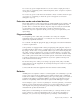
Replacing the microprocessor Important Before you install or remove any component, read “Important safety information” on page v. These precautions and guidelines will help you work safely. 1. Take notice of the orientation of the beveled corner on the microprocessor 2 . This is important when reinstalling the microprocessor on the system board. 2. Make sure that the handle used to remove the microprocessor is fully in the up position.
Microprocessor 0.01 mL of thermal grease Note: 0.01ML is one tick mark on the syringe. If the grease is properly applied, approximately half (0.22ML) of the grease will remain in the syringe. 8. Place the heat sink into position on the microprocessor and replace the air baffle over the heat sink. 9. When tightening the screws that clamp the heat sink, do not overtighten. Tighten the clamp screws evenly by tightening one side some and then the other until they are both snug.
4. Remove the PCI riser and PCI adapters that impede access to the battery. 5. Remove the old battery. 6. Install the new battery. 7. Install the PCI riser and adapters if removed. 8. Replace the cover, and connect the cables. See “Closing the cover and connecting the cables” on page 25. Note: When the computer is turned on for the first time after battery replacement, an error message might be displayed. This is normal after replacing the battery. 9. Turn on the computer and all attached devices. 10.
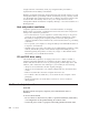
7. Install the new speaker and reconnect the speaker cable. 8. Lower the drive bay assembly. 9. Replace the cover, and connect the cables. See “Closing the cover and connecting the cables” on page 25. Figure 1. Speaker, fan, power button and LED assembly 1 2 3 speaker power button and LED assembly fan Removing and replacing the power button and LED assembly Important Before you install or remove any component, read “Important safety information” on page v.
5. Lift the tab and slide the power button and LED assembly 2 out. See Figure 1 on page 43. 6. Install the new power button and LED assembly and reconnect the power button and LED assembly cable. 7. Lower the drive bay assembly. 8. Replace the cover, and connect the cables. See “Closing the cover and connecting the cables” on page 25. Removing and replacing the fan assembly Important Before you install or remove any component, read “Important safety information” on page v.
5. Remove the plastic insert behind the bezel by releasing the tabs as shown: 6. Remove the fan assembly by releasing the tabs out as shown. 7. Install the new fan assembly and connect the fan cable to the system board. 8. 9. 10. 11. Reinstall the plastic insert. Reinstall the front bezel. Lower the drive bay assembly. Replace the cover, and connect the cables. See “Closing the cover and connecting the cables” on page 25. Appendix A.
Completing the installation After replacing the CRUs, you need to close the cover and reconnect cables, including telephone lines and power cords. Also, depending on the CRU that was replaced, you might need to confirm the updated information in the IBM Setup Utility program. To complete the CRU installation: 1. Ensure that all components have been reassembled correctly and that no tools or loose screws are left inside your computer. 2. Clear any cables that might impede the replacement of the cover. 3.
Appendix B. Updating POST/BIOS This appendix contains information about updating POST/BIOS and how to recover from a POST/BIOS update failure. POST/BIOS POST and BIOS are the basic layer of software that is built into your computer. They include the power-on self-test (POST), the basic input/output system (BIOS) code, and the IBM Setup Utility program. POST is a set of tests and procedures that is performed each time you turn on your computer.
Scroll down and look for a .txt file that has instructions for Flash BIOS update from the operating system. Click the .txt file. 7. Print these instructions. This is very important since they are not on the screen after the download begins. 8. From your browser, Click Back to return to the list of files. Carefully follow the printed instructions to download, extract, and install the update. 6.
Appendix C. Cleaning the mouse This appendix provides instructions on how to clean your mouse. The procedure will be different depending on which type of mouse you have. Cleaning an optical mouse If you experience some problems with your optical mouse, check the following: 1. Turn the mouse over and look carefully at the lens area. a. If there is a smudge on the lens, gently clean the area with a plain cotton swab or plain q-tip. b.
To clean a mouse with a ball: 1. Turn off your computer. 2. Turn the mouse over, with the top side down, and look carefully at the bottom. Twist the retainer ring 1 to the unlocked position to remove the ball. 3. Place your hand over the retainer ring and ball 2 , and then turn the mouse over, top side up, so that the retainer ring and ball fall out into your hand. 4. Wash the ball in warm, soapy water then dry it with a clean cloth. Blow air carefully into the ball cage 4 to dislodge dust and lint. 5.
Appendix D. Manual modem commands The following section lists commands for manually programming your modem. Commands are accepted by the modem while it is in Command Mode. Your modem is automatically in Command Mode until you dial a number and establish a connection. Commands may be sent to your modem from a PC running communication software or any other terminal devices. All commands sent to the modem must begin with AT and end with ENTER.
Command Function H1 Force modem off-hook (make busy) Note: H1 command is not supported for Italy I_ L_ M_ I0 Display product-identification code I1 Factory ROM checksum test I2 Internal memory test I3 Firmware ID I4 Reserved ID L0 Low speaker volume L1 Low speaker volume L2 Medium speaker volume L3 High speaker volume M0 Internal speaker off M1 Internal speaker on until carrier detected M2 Internal speaker always on M3 Internal speaker on until carrier detected and off while d
Extended AT commands Command Function &C0 Force Carrier Detect Signal High (ON) &C1 Turn on CD when remote carrier is present &D0 Modem ignores the DTR signal &D1 Modem returns to Command Mode after DTR toggle &D2 Modem hangs up, returns to the Command Mode after DTR toggle &D3 Resets modem after DTR toggle &F_ &F Recall factory default configuration &G_ &G0 Guard tone disabled &G1 Guard tone disabled &G2 1800 Hz guard tone &K0 Disable flow control &K3 Enable RTS/CTS hardware flow
Command Function &W_ %E_ &V1 Display Last Connection Statistics &W0 Stores the active profile as Profile 0 &W1 Stores the active profile as Profile 1 %E0 Disable auto-retrain %E1 Enable auto-retrain +MS? Displays the current Select Modulation settings +MS=? Displays a list of supported Select Modulation options +MS=a,b,c,e,f Select modulation where: a=0, 1, 2, 3, 9, 10, 11, 12, 56, 64, 69; b=0-1; c=300-56000; d=30056000; e=0-1; and f=0-1. A, b, c, d, e, f default=12, 1, 300, 56000, 0, 0.
Fax Class 1 commands +FAE=n Data/Fax Auto Answer +FCLASS=n Service Class +FRH=n Receive data with HDLC framing +FRM=n Receive data +FRS=n Receive silence +FTH=n Transmit data with HDLC framing +FTM=n Transmit data +FTS=n Stop transmission and wait Fax Class 2 commands +FCLASS=n Services class. +FAA=n Adaptive answer. +FAXERR Fax error value. +FBOR Phase C data bit order. +FBUF? Buffer size (read only). +FCFR Indicate confirmation to receive. +FCLASS= Service class.
+FPHCTO Phase C time out. +FPOLL Indicates polling request. +FPTS: Page transfer status. +FPTS= Page transfer status. +FREV? Identify revision. +FSPT Enable polling. +FTSI: Report the transmit station ID.
Attention Switzerland User: If your Swisscom phone line does not have Taxsignal switched OFF, modem function may be impaired. The impairment may be resolved by a filter with the following specifications: Telekom PTT SCR-BE Taximpulssperrfilter-12kHz PTT Art. 444.112.7 Bakom 93.0291.Z.N Appendix D.
58 User Guide
Appendix E. Notices IBM may not offer the products, services, or features discussed in this document in all countries. Consult your local IBM representative for information on the products and services currently available in your area. Any reference to an IBM product, program, or service is not intended to state or imply that only that IBM product, program, or service may be used.
Trademarks The following terms are trademarks of the IBM Corporation in the United States or other countries or both: IBM PS/2 ThinkCentre Wake on LAN Intel, Celeron, and Pentium are trademarks of Intel Corporation in the United States, other countries, or both. Microsoft, Windows, and Windows NT are trademarks of Microsoft Corporation in the United States, other countries, or both. Other company, product, and service names may be trademarks or service marks of others.
Index Special characters .
modem commands (continued) Fax Class 2 55 MNP/V.42/V.42bis/V.
Part Number: 13R9208 Printed in USA (1P) P/N: 13R9208