
Desktop Computer Hardware Maintenance Manual
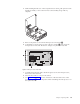
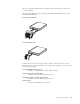
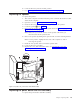

10. Remove the microprocessor 2 from the system board by lifting the small
handle 1 on the microprocessor. Carefully lift the microprocessor out of the
socket.
v If you are installing a new system board assembly, continue at Step 11.
v If you are replacing only the microprocessor, go to “Replacing the
microprocessor” on page 38.
11.
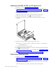
Carefully take note of the location of all cable connections on the system
board. It will be necessary to reconnect them properly when installing a new
system board assembly.
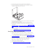
12. Take note of the cable routing. It is important to route the cables properly
when installing the new system board.
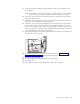
13. Disconnect the diskette drive cable from the system board by sliding the
plastic cable retainer upward to release the cable.
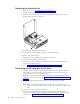
14. Disconnect all other cables connected to the system board.
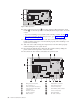
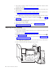
1 Microprocessor heat sink 8 Diskette drive connector
2 Fan connectors (2) 9 Front panel connector
3 memory module connectors (2) 10 Power connector (P1)
4 SATA 1 IDE and SATA 2 IDE
connectors (2)
11 PATA Primary IDE connector
5 PCI riser connector 12 Power connector (P2)
6 Speaker connector 13 Heat sink clamps
7 POV connector 14 CD audio connector
Figure 2. Microprocessor
36 Hardware Maintenance Manual