ThinkCentre™ Hardware Replacement Guide Types 8122, 8123, 8124 Types 8131, 8137, 8138
ThinkCentre™ Hardware Replacement Guide Types 8122, 8123, 8124 Types 8131, 8137, 8138
First Edition (April 2005) © Copyright International Business Machines Corporation 2005. All rights reserved. US Government Users Restricted Rights – Use, duplication or disclosure restricted by GSA ADP Schedule Contract with IBM Corp.
Contents Overview . . . . . . . . . . . . . . v Safety information for replacing CRUs . . . . . . v Safety information for replacing FRUs . . . . . . v Additional information resources . . . . . . . v Tools required . . . . . . . . . . . . . vi Handling static-sensitive devices . . . . . . . vi Chapter 1. Locations . . . . . . . . . 1 Locating components . . . . . . . . . Locating controls and connectors on the front of computer . . . . . . . . . . . . .
iv Hardware Replacement Guide
Overview This guide is intended to be used by customers who are replacing Customer Replaceable Units (CRUs) as well as trained service personnel who are replacing Field Replaceable Units (FRUs). In this guide CRUs and FRUs will often be referred to as parts. This guide does not include procedures for all parts. It is expected that cables, switches, and certain mechanical parts can be replaced by trained service personnel without the need for step-by-step procedures. Note: Use only the parts provided by IBM.
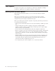
Tools required To replace some parts in your computer, you will need a flat-blade or Phillips screwdriver. Additional tools might be needed for certain parts. Handling static-sensitive devices Static electricity, although harmless to you, can seriously damage computer components. When you are replacing a part, do not open the static-protective package containing the new part until the defective part has been removed from the computer and you are ready to install the new part.
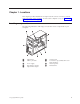
Chapter 1. Locations This chapter provides illustrations to help locate the various connectors, controls and components of the computer. To remove the computer cover, see “Removing the computer cover” on page 5. Locating components The following illustration will help you locate the various components in your computer. 1 2 Optical drive Memory modules 6 7 3 4 5 Power supply PCI adapter connector Optional PCI adapter 8 9 © Copyright IBM Corp.
Locating controls and connectors on the front of the computer This section shows the various external connectors on the computer to which you can attach external devices.
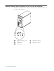
Locating connectors on the rear of the computer The following illustration shows the location of connectors on the rear of the computer.
Identifying parts on the system board The system board (sometimes called the planar or motherboard) is the main circuit board in your computer. It provides basic computer functions and supports a variety of devices. The following illustration shows the locations of parts on the system board.
Chapter 2. Replacing hardware Attention: Do not remove the computer cover or attempt any repair before reading the “Important safety information” in the Quick Reference that was included with your computer or in the Hardware Maintenance Manual (HMM) for the computer. To obtain copies of the Quick Reference or HMM, go to http://www.ibm.com/pc/support. Note: Use only the parts provided by IBM.
6. Some models have an optional hard disk drive mounting bracket 1 installed. When this bracket is installed, access to some of the CRUs or FRUs inside the chassis is restricted. Note: There appears to be two drive bays in the bracket. However, due to thermal restrictions, only the bay 2 at the rear of the chassis can be used to install a hard disk drive. See “Pivoting or removing the optional hard disk drive mounting bracket” on page 7.
Pivoting or removing the optional hard disk drive mounting bracket The optional hard disk drive mounting bracket can easily be pivoted upward or removed if necessary to enable replacement of some CRUs and FRUs. To pivot the optional hard disk drive bracket upward, pull outward at the bottom of the bracket. Note: You might have to disconnect the cables attached to the optional hard disk drive.
Removing and replacing the front bezel 1. Remove the computer cover. See “Removing the computer cover” on page 5. 2. To release the front bezel from the chassis, press downward on the two plastic tabs 1 and push the bezel outward as shown. 3. To reinstall the bezel, align the plastic tabs 1 on the bottom of the bezel with the corresponding holes in the chassis, then snap it into position at the bottom and top of the chassis. 4. Go to “Completing the installation” on page 33.
2. To access the 12 V power connector, remove the lower drive cage thumb-screw and slide the lower drive cage toward the rear and out of the bay. Place the drive cage out of your way without disconnecting the drive signal cables. 3. Disconnect the power supply cables 1 and 2 from the system board. 4. Disconnect the power cable from each of the drives. Note the location of each cable that is disconnected. Chapter 2.
5. Remove the four screws that secure the power supply at the rear of the chassis. 6. Press inward on the metal retainer inside the chassis and slide the power supply toward the front of the chassis and lift it out of the chassis as shown. 7. Install the new power supply into the chassis so that the screw holes in the power supply align with those in the chassis. Note: Use only the screws provided with the new power supply. 8. Install and tighten the four screws that secure the power supply.
9. Reconnect power supply connectors 1 and 2 to the system board. 10. Reinstall the lower drive cage and secure it with the thumb-screw. 11. Reconnect a power supply connector to each of the drives. 12. Go to “Completing the installation” on page 33. Chapter 2.
Replacing the system board assembly Attention: Do not remove the computer cover or attempt any repair before reading the “Important safety information” in the Quick Reference that was included with your computer or in the Hardware Maintenance Manual (HMM) for the computer. To obtain copies of the Quick Reference or HMM, go to http://www.ibm.com/pc/support. 1. Turn off the computer and allow it to cool for one hour. 2. Remove the computer cover. See “Removing the computer cover” on page 5.
6. Remove the lower drive cage by removing the thumb-screw and sliding the lower drive cage toward the rear of the computer. 7. Disconnect the cables attached to the drives in the lower drive cage and set the drive cage to the side. 8. Disconnect all cables connected to the system board. See “Identifying parts on the system board” on page 4. 9. Remove screws 1 through 7 . 10. Slide the system board toward the front of the computer to disengage it from the mounting tabs and lift it out. 11.
13. Release and pivot lever 1 upward. Remove the heat sink 2 from the system board by carefully lifting it up and off the mounting bracket. Place the heat sink on its side on a clean, flat surface so the thermal material on the bottom of the heat sink does not touch the surface and become contaminated. 14. Release and pivot locking lever 2 securing the microprocessor 1 , then pivot the microprocessor retainer 3 until it is open.
15. Using the vacuum pen 1 , remove the microprocessor from the system board socket by lifting it straight up and out of the socket. Important Do not touch the gold contacts on the bottom of the microprocessor. If you must touch the microprocessor, touch only the sides. Notes: a. Notice of the orientation of the notches 1 on the microprocessor. This is important when reinstalling the microprocessor on the new system board. b. Do not drop anything onto the microprocessor socket while it is exposed.
16. On the new system board, release and pivot the locking lever, then pivot the microprocessor retainer until it is open. Note: There will be a black protective cover on the retainer to protect the microprocessor socket. As you close the microprocessor retainer, remove the cover. Place the black protective cover on the microprocessor retainer of the defective system board. 17. Position the microprocessor so that the notches on the microprocessor are aligned with the tabs in the microprocessor socket.
19. Pivot the microprocessor retainer 3 to the closed position and rotate the locking lever 2 to secure the microprocessor 1 . Make sure the locking lever is engaged with the retainer tab when securing the microprocessor. 20. Align the beveled corners of the heat sink and the mounting bracket. Then position the heat sink 2 on the heat sink mounting bracket. Lower the lever 1 to secure the heat sink. Chapter 2.
21. Install the new system board assembly into the computer chassis by aligning the four slots in the metal plate on the bottom of the system board with the tabs in the chassis. Then slide the system board toward the rear of the chassis. Important Make sure to correctly align the metal plate on the bottom of the system board with the tabs in the chassis. Otherwise, the system board might be damaged when you install the screws. 22. Align the seven screw holes, and install the screws. 23.
Replacing the microprocessor Attention: Do not remove the computer cover or attempt any repair before reading the “Important safety information” in the Quick Reference that was included with your computer or in the Hardware Maintenance Manual (HMM) for the computer. To obtain copies of the Quick Reference or HMM, go to http://www.ibm.com/pc/support.
2. Remove the air baffle by squeezing the tabs 1 together and pulling it out of the chassis. 3. Release and pivot lever 1 upward. Remove the heat sink 2 from the system board by carefully lifting it up and off the mounting bracket.
4. Release and pivot locking lever 2 securing the microprocessor 1 , then pivot the microprocessor retainer 3 until it is open. 5. Using the vacuum pen 1 , remove the microprocessor from the system board socket by lifting it straight up and out of the socket. Important Do not touch the gold contacts on the bottom of the microprocessor. If you must touch the microprocessor, touch only the sides. Chapter 2.
Notes: a. Notice of the orientation of the notches 1 on the microprocessor. This is important when reinstalling the microprocessor on the system board. b. Do not drop anything onto the microprocessor socket while it is exposed. The socket pins must be kept as clean as possible. 6. Make sure that the microprocessor retainer is fully open. 7. Loosen the protective cover 3 that protects the gold contacts on the new microprocessor 2 but do not remove it.
Important To avoid damaging the microprocessor contacts, do not tilt the microprocessor when installing it into the socket. 9. Using the vacuum pen 1 , lower the microprocessor straight down into the microprocessor socket. Note: Install the black protective cover that was removed from the new microprocessor onto the defective microprocessor after the installation is complete. 10. Pivot the microprocessor retainer 3 to the closed position and pivot the locking lever 2 to secure the microprocessor 1 .
11. Align the beveled corners of the new heat sink and the mounting bracket. Then position the heat sink 2 on the heat sink mounting bracket. Lower the lever 1 to secure the heat sink. 12. Reinstall the air baffle. 13. Go to “Completing the installation” on page 33.
Replacing a memory module Attention: Do not remove the computer cover or attempt any repair before reading the “Important safety information” in the Quick Reference that was included with your computer or in the Hardware Maintenance Manual (HMM) for the computer. To obtain copies of the Quick Reference or HMM, go to http://www.ibm.com/pc/support. 1. Remove the computer cover. See “Removing the computer cover” on page 5. Note: For this procedure, it helps to lay the computer on its side. 2.
Replacing an adapter Attention: Do not remove the computer cover or attempt any repair before reading the “Important safety information” in the Quick Reference that was included with your computer or in the Hardware Maintenance Manual (HMM) for the computer. To obtain copies of the Quick Reference or HMM, go to http://www.ibm.com/pc/support. 1. Remove the computer cover. See “Removing the computer cover” on page 5. Note: For this procedure, it helps to lay the computer on its side. 2.
Replacing the hard disk drive Attention: Do not remove the computer cover or attempt any repair before reading the “Important safety information” in the Quick Reference that was included with your computer or in the Hardware Maintenance Manual (HMM) for the computer. To obtain copies of the Quick Reference or HMM, go to http://www.ibm.com/pc/support. Important When you receive a new hard disk drive, you will also receive a Product Recovery CD.
6. To install the new hard disk drive into the blue bracket, flex the bracket and align the pins 1 through 4 on the bracket with the holes in the hard disk drive. Do not touch the circuit board 5 on the bottom of the hard disk drive. 7. Insert the new hard disk drive into the lower drive cage with its circuit board side facing downward. 8. Connect the power and signal cables to the new hard disk drive. See “Identifying parts on the system board” on page 4. 9.
3. Disconnect the signal and power cables from the rear of the optical drive. 4. Release the optical disk drive by pressing on the blue retainer lever at the side of the drive and removing it from the front of the computer. 5. Remove the retainer bracket from the failing drive and install it on the new drive. 6. Slide the new optical drive into the bay from the front until it snaps into position. 7. Reconnect the signal and power cables to the drive. 8. Reinstall the front bezel.
Replacing the diskette drive Attention: Do not remove the computer cover or attempt any repair before reading the “Important safety information” in the Quick Reference that was included with your computer or in the Hardware Maintenance Manual (HMM) for the computer. To obtain copies of the Quick Reference or HMM, go to http://www.ibm.com/pc/support. 1. Remove the computer cover. See “Removing the computer cover” on page 5. 2. Remove the front bezel. See “Removing and replacing the front bezel” on page 8.
1. Remove any media (diskettes, CDs, or tapes) from the drives, shut down the computer, and turn off all attached devices. 2. Unplug all power cords from electrical outlets. 3. Locate the connector for the keyboard. See “Locating connectors on the rear of the computer” on page 3 and “Locating controls and connectors on the front of the computer” on page 2.
1. Remove the computer cover. See “Removing the computer cover” on page 5. Note: For this procedure, it helps to lay the computer on its side. 2. Remove the air baffle by squeezing the two tabs 1 together and pulling it out of the chassis. 3. Locate the internal speaker connector, see “Identifying parts on the system board” on page 4. 4. Disconnect the speaker cable from the system board. 5. Slide the speaker 1 upward until it is free from the metal tabs that secure it at the bottom.
Completing the installation After replacing a failed part, you need to install any other removed parts, install the computer cover, and reconnect any cables, including telephone lines and power cords. Also, depending on the part that was replaced, you might need to confirm the updated information in the Setup Utility program. See ″Starting the Setup Utility″ in your Quick Reference or in the Hardware Maintenance Manual. To complete the installation: 1.
5. Reconnect the external cables. Plug the power cord into the computer then into a properly grounded power receptacle. See “Locating controls and connectors on the front of the computer” on page 2 and “Locating connectors on the rear of the computer” on page 3. 6. If you are replacing the system board you must update (flash) the BIOS. See “Updating (flashing) BIOS from a diskette or CD-ROM.” 7.
Part Number: 39J7784 Printed in USA (1P) P/N: 39J7784