Supplement to the RS/6000 7043 43P Series (SA38-0511 and SA38-0512) IBM Service Guide and User’s Guide SN32-9080-01
Second Edition (December 2000) Before using this information and the product it supports, read the information in “Appendix. Notices” on page 15. ©International Business Machines Corporation 2000. All rights reserved. Note to U.S. Government Users - Documentation related to restricted rights - Use, duplication, or disclosure is subject to the restrictions set forth in the GSA ADP Schedule Contract with IBM Corp..
Contents About This Book . . . . . . . . . . . . . . . . . . . . . . . v ISO 9000 . . . . . . . . . . . . . . . . . . . . . . . . . . v Online Publications . . . . . . . . . . . . . . . . . . . . . . . v Related Publications . . . . . . . . . . . . . . . . . . . . . . v Trademarks . . . . . . . . . . . . . . . . . . . . . . . . . v Chapter 1. 7043–140 and 7043–150 Fansink Removal and Replacement Procedures . . . . . . . . . . . . . . . . . . . . Identifying the Fansink Number . . . . . . . . . . . . . . .
iv Supplement to the Service Guide and User’s Guide
About This Book This supplement provides updates to the following publications: v RS/6000 7043 43P Series User’s Guide, SA38-0511 v RS/6000 7043 43P Series Service Guide, SA38-0512 ISO 9000 ISO 9000 registered quality systems were used in the development and manufacturing of this product. Online Publications RS/6000 and pSeries 680 publications are available online. To access the online books, visit our Web site at: http://www.rs6000.ibm.
vi Supplement to the Service Guide and User’s Guide
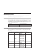
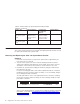
Chapter 1. 7043–140 and 7043–150 Fansink Removal and Replacement Procedures This chapter provides information on replacing defective 7043–140 and 7043–150 fansinks without having to replace the entire system board. Identifying the Fansink Number The following table contains information to help you determine the correct fansink to be replaced on both the 7043–140 and 7043–150 system boards. Obtain the correct fan(s) before going on-site to replace the fansink assembly.
Table 2. Fansink numbers by System Board Assembly and FRU Numbers (continued).
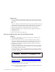
4. To remove the disk drive bracket, refer to the ″Removing Internal Drive″ section of the RS/6000 7043–43P Series Service Guide. Carefully place the bracket assembly on top of the power supply (leave the hard files plugged in). Note: Disconect temporarily any PCI Adapter Card installed in slot 5 in order to remove the disk drive bracket. 5. Locate the CPU fansink on the planar under the disk drive and unplug it. Fansink Location 6. Unclip the heatsink by pushing down and away on the finger tab. 7.
Replacement 1. If you are replacing a fansink 09P1125, install the new component by hooking the side opposite the finger tab and then pushing the finger tab side down until it locks into position. OR If you are replacing a fansink 09P1126, first remove the paper pull tab to expose the thermal grease underneath. Install the new fansink by hooking the side opposite the finger tab and then pushing the finger tab side down until it locks into position. 2.
5. Locate and unplug the fan and disconnect the fansink assembly power cable from the CPU fansink connector (J26). Note: There are two possible fansink connections for this system board: right-angle finger tabs, and wire springs. Fansink Location 6. To remove a fansink with right-angle finger tabs, unclip the heatsink by pushing down and away on the fingertab. Remove the fansink assembly and discard.
Replacement 1. If you are replacing a fansink 09P1126, first remove the paper pull tab to expose the thermal grease underneath. Install the new fansink by hooking the side opposite the finger tab and then pushing the finger tab side down until it locks into position. OR If you are replacing a fansink 09P1129, remove the adhesive protective paper on the bottom of the heatsink and place the fansink assembly into the metal bracket on the system board assembly.
Chapter 2. 7043–150 System Features This chapter contains information specific to both the 250MHz and 375MHz options for the Model 150, and applies to the RS/6000 7043 43P Series User’s Guide and the RS/6000 7043 43P Series Service Guide. All other information is consistent with the system books.
Keyboard and Mouse v Standard: 101–Key Enhanced keyboard v Optional: 101/102 or 106–Key Enhanced Keyboard v Standard: 3-button mouse Front-Panel Display v 4-digit LED diagnostics display Input/Output Ports v 25-pin Parallel v 9-pin Serial (2) v 8-pin Tablet v Keyboard v Mouse v Ultra SCSI (16-bit) v 100/10 Base 5 Ethernet v 100/10 Base T Ethernet v Audio Line-in and Audio Line-out v Microphone v Headphone Security Features v Cover lock v Tie-down (optional) v Power-on password v Privileged-access passwor
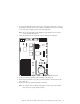
Setting the SCSI Security Jumpers Note: Carefully read and follow the safety guidelines detailed in the corresponding section of the RS/6000 7043 43P Series User’s Guide, SA38-0511. To increase system unit security, the external SCSI connector can be disabled by changing jumpers inside the system unit. 1. Locate the SCSI security jumpers in the following figure. 2. To disable the external SCSI connector, move the jumper on J35 to the front two pins, and move the jumper on J36 to the rear two pins.
System Board Locations for Model 150 10 B1 Battery connector J1 Wakeup-on-LAN jumper J2 5x5 Auxiliary 5v connector J3 Audio input connector J4 Internal SCSI connector #2 J5 CD-ROM audio connector J6 CD-ROM audio connector J7 Power connector J8 Power connector J10 Media fan connector J11 Memory Connector 1 Supplement to the Service Guide and User’s Guide
J13 Audio output connector J15 Remote Power-up Jumper J16 Diskette drive connector J17 Microphone jack J18 Reset Connector J19 Memory Connector 3 J20 Power-on Password jumper J22 Headphone jack J23 Serial port connector 2 J24 Serial port connector 1 J25 Tablet port connector J26 CPU fansink connector J27 System fan connector J28 Memory Connector 2 J30 System fan connector J32 Privileged-Access Password jumper J33 Internal SCSI 16-bit connector J35 SCSI security jumper J36
System Board, Cables, and Accessories 12 Supplement to the Service Guide and User’s Guide
Index Number FRU Number Units Per Assy Description 1 2 3 4 09P0168 27F4212 39H8697 19L1808 1 6 1 1-4 System Board (250 MHz) Screw Hex Standoff 64MB DIMM 5 6 7 8 9 10 11 12 13 19L1809 29L3302 93H1821 40H7572 93H6151 08L1417 07L9115 40H6328 11H2168 15F8409 65G8850 1-4 1-4 1 1 1 1 1 2 1 1 1 128MB DIMM 256MB DIMM Diskette Cable Assembly SCSI Cable Assembly Ultra Cable Assembly (Optional) Riser Card Vertical Stand 9-pin to 25-pin Serial Port Converters Display Cable Toroid Kit Battery CD-ROM drive aud
14 Supplement to the Service Guide and User’s Guide
Appendix. Notices This information was developed for products and services offered in the U.S.A. The manufacturer may not offer the products, services, or features discussed in this document in other countries. Consult the manufacturer’s representative for information on the products and services currently available in your area. Any reference to the manufacturer’s product, program, or service is not intended to state or imply that only that product, program, or service may be used.
16 Supplement to the Service Guide and User’s Guide
Reader’s Comments — We’d Like to Hear From You Supplement to the RS/6000 7043 43P Series Service Guide and User’s Guide Order Number: SN32–9080–01 Overall how satisfied are you with the information in this book? Overall Satisfaction Very Satisfied Satisfied h h Neutral Dissatisfied Very Dissatisfied h h h How satisfied are you that the information in this book is: Accurate Complete Easy to find Easy to understand Well organized Applicable to your tasks Very Satisfied Satisfied h h h h h h h h
Cut or Fold Along Line Fold and Tape Please do not Staple Fold and Tape NO POSTAGE NECESSARY IF MAILED IN THE UNITED STATES BUSINESS REPLY MAIL POSTAGE WILL BE PAID BY ADDRESSEE Information Development Department H6DS-9561 11400 Burnet Road Austin, TX 78758-3493 Fold and Tape Please do not Staple Fold and Tape Cut or Fold Along Line 18 Supplement to the Service Guide and User’s Guide
IBMR Part Number: 09P2506 Printed in the United States of America on recycled paper containing 10% recovered post-consumer fiber.